Try Our Live Demo
Why UML notation matters
Software design involves more than one kind of question: what does the system look like, how does it behave, and how do its parts talk to each other. UML has a dedicated notation for each.
Precise language for software design
UML shapes and relationships mean the same thing to every engineer who reads them, without a legend.
Structure, behavior, and interaction, all covered
Class diagrams describe what a system is made of, activity diagrams describe what it does, and sequence diagrams describe how its parts communicate.
One tool for every view
Class, activity, and sequence diagrams are built with the same diagram surface, editing model, and export options.
Classes and interfaces
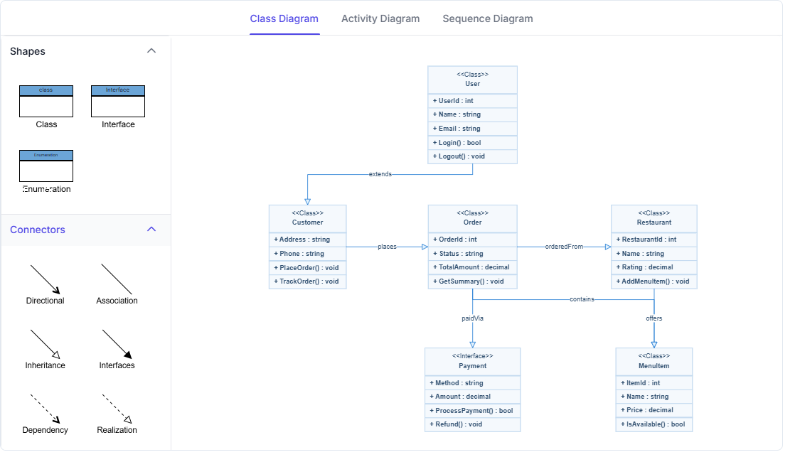
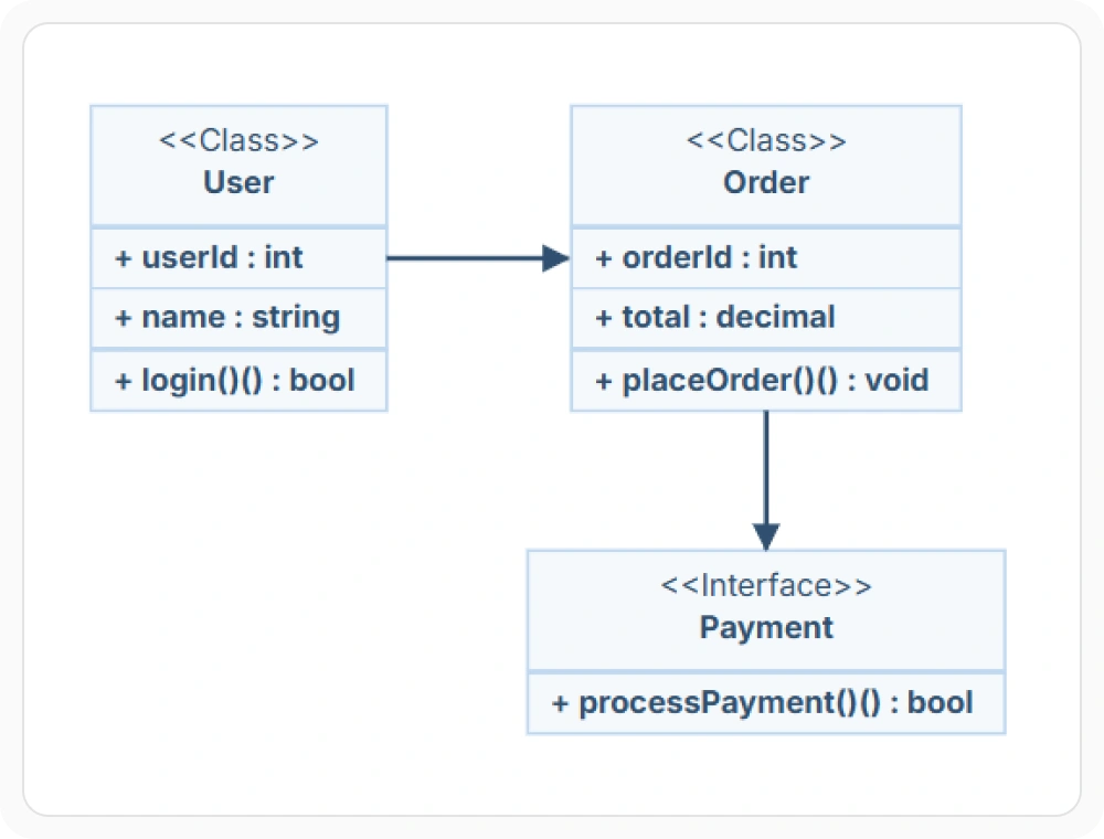
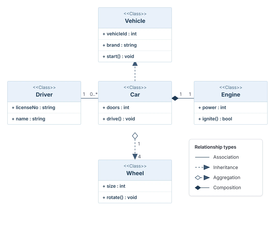
A class diagram describes the static structure of a system using classes and interfaces, each listing its own attributes and methods. Use a class diagram when a system’s structure needs to be documented before implementation begins.
- Provide a class that lists its name, attributes, and methods, with each member’s data type and visibility
- Support an interface that follows the same structure as a class, describing a contract rather than an implementation
- Enable in-place editing of a class or interface shape through a text editor split into name, attribute, and method sections
- Deliver class diagram shapes that can be generated from existing business logic instead of built manually
Relationships between classes
A connector between two classes carries a specific meaning in UML, rather than a single generic line standing in for every kind of relationship. Use UML relationship connectors when the structural links between classes need to be precise and standardized.
- Provide an association as a general link between two classes
- Support inheritance, also called generalization and shown with a hollow triangle, to connect a subclass to its superclass
- Deliver aggregation, shown with a hollow diamond, and composition, a stronger form, to represent whole-part relationships
- Enable multiplicity labels to specify how many instances participate on each side, such as one-to-one or many-to-one
Modeling a workflow with activity shapes
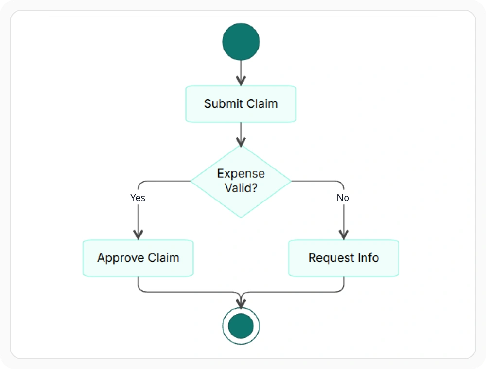
An activity diagram is a flowchart-like view of a system’s behavior, using UML-specific shapes instead of generic flowchart notation. Use an activity diagram when a system’s behavior, including parallel flow, needs to be modeled in UML notation.
- Provide initial and final nodes to mark where the activity flow starts and ends
- Support action shapes to represent single steps and decision shapes to represent branching points
- Deliver fork and join nodes to split a flow into parallel paths and bring them back together, and merge nodes to combine multiple paths without parallel execution
- Enable time event, accepting event, and send or receive signal shapes to represent activity triggered by timing or by messages
Sequence diagram interaction over time
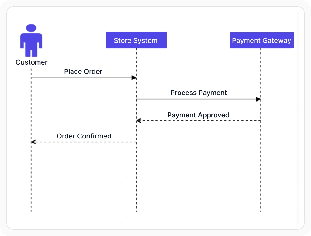
A sequence diagram shows how a fixed set of participants exchange messages over time, rather than how a single process branches. Use a sequence diagram when object interactions over time need to be documented in UML notation.
- Provide each participant with a lifeline extending down through the diagram from its position at the top
- Support activation boxes to mark the period a participant is actively processing a message
- Deliver messages drawn as arrows crossing between participant lifelines
- Enable fragments to group related messages under a shared condition such as a loop or an alternative path
Building from a symbol palette
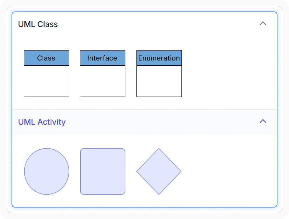
UML shapes for class, activity, and sequence diagrams can be added from a symbol palette instead of being configured one property at a time. Use the symbol palette when UML shapes need to be assembled through drag-and-drop rather than programmatic configuration.
- Provide predefined UML shapes, including classes with their own attributes and methods, that can be dragged onto the diagram surface
- Support connecting two shapes with a specific relationship, such as inheritance, using the same connector mechanism as any other diagram
- Deliver UML shapes from the palette across JavaScript, Angular, React, Vue, Blazor, ASP.NET Core, and MVC platforms
- Enable general symbol palette configuration as covered in Symbol Palette
PLATFORM SUPPORT
UML support by platform
UML class shapes are available on most Diagram SDK platforms, but activity shapes, the newer sequence diagram model, and palette support are not confirmed as equally complete everywhere. JavaScript, Angular, React, Vue, ASP.NET Core, ASP.NET MVC, and Blazor share a common UML shape model, while WPF exposes UML shapes through its own resource dictionary.
| Capability | JavaScript frameworks | ASP.NET Core and MVC | Blazor | WPF | UWP | Windows Forms |
|---|---|---|---|---|---|---|
| UML class and interface shapes | ||||||
| UML activity diagram shapes | ||||||
| UML sequence diagram model | ||||||
| UML shapes available from a symbol palette |
Frequently Asked Questions
What’s the difference between a class and an interface in a UML diagram?
Both list attributes and methods in the same visual structure, but a class represents an implementation while an interface represents a contract that an implementation must fulfill.
How is a UML activity diagram different from a generic flowchart?
Both describe a sequence of steps, but a UML activity diagram uses its own defined shapes, such as fork and join nodes for parallel flow, rather than the general-purpose symbols used in a flowchart; see Flowchart Diagrams.
Can a UML class diagram be generated automatically instead of built by hand?
Yes, where automatic generation from business logic is supported, class diagram shapes can be produced directly from an existing model instead of being placed one at a time.
Is UML support identical across every platform?
No. Class diagram shapes are the most broadly documented. Activity shapes, the sequence diagram model, and palette support are newer or less consistently documented across platforms, as shown in the table above.
What do the different UML relationship types mean?
Association is a general link. Inheritance shows one class extending another. Aggregation shows a whole made of parts that could exist independently, and composition shows a stronger version of that relationship where the parts depend on the whole.
What does an activation box represent in a sequence diagram?
It marks the period during which a participant is actively processing a message, drawn as a thin rectangle over that participant’s lifeline.
Can a UML sequence diagram be exchanged as text?
Yes, where Mermaid support for sequence diagrams is available. See Data Import & Export for how Mermaid import and export work.
Resources
Learn more about our Diagram SDK
Explore demos, documentation, and support resources to get the most out of the Syncfusion Diagram SDK.
Review shared concepts and supported platforms
Representative UML class diagram demo
See classes, interfaces, and relationships in action
Ask, share, and connect with peers
Find solutions and best practices fast
Get expert help when needed
Feature requests and bug reports
Track issues and suggest improvements
Awards
Greatness—it’s one thing to say you have it, but it means more when others recognize it. Syncfusion® is proud to hold the following industry awards.