Try Our Live Demo
Why entity relationship diagrams matter
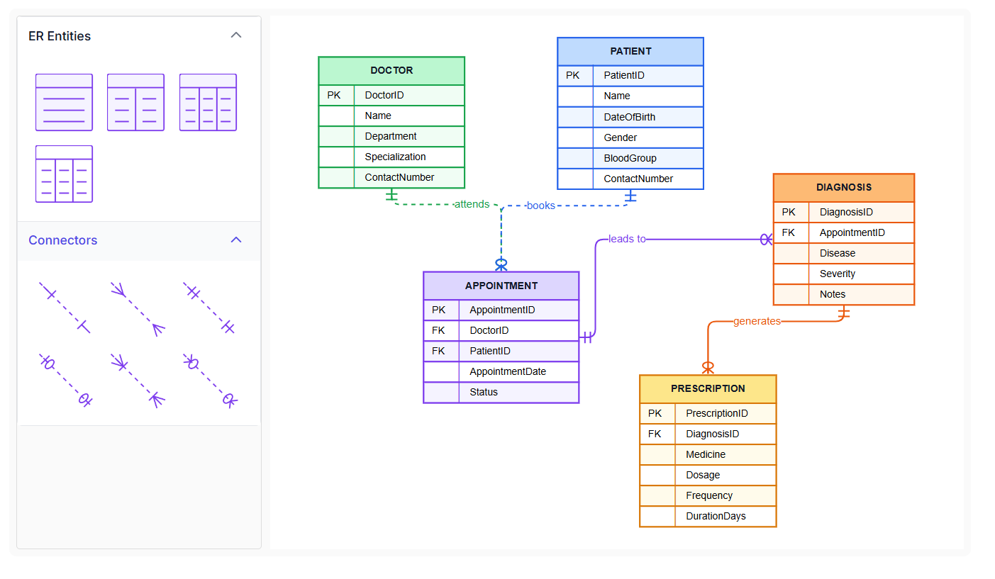
A database schema described only in code is hard to review as a whole. A dedicated entity shape with real fields and cardinality, plus ready-made variations to start from, keeps that structure both accurate and readable.
A shape built for databases
A dedicated entity shape renders a header and field rows automatically, instead of a generic box standing in for a table.
Cardinality built in, not bolted on
Crow’s Foot symbols come from a dedicated connector type, not lines styled by hand to look like a relationship.
Start from a ready example
Predefined entities and relationship connectors in the symbol palette give a working starting point instead of an empty shape.
Entities as structured shapes
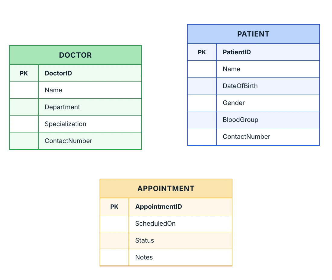
An entity is a dedicated shape built specifically for this purpose, rather than a generic box styled to look like one. It displays a header naming the entity and a list of its fields as rows, similar to a small database table. Use an entity shape when a database table needs to be represented with its fields in a structured, recognizable layout.
- Provide a dedicated entity shape type that renders the header and field rows automatically
- Support independent customization of the header’s text and appearance separately from the fields
- Ensure a single default field is added automatically when no fields are specified
- Deliver predefined entity shapes from a symbol palette; see Symbol Palette
Field details and constraints
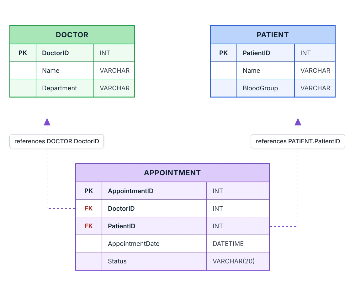
Each field in an entity can carry more than just a name. Its data type and any constraints it enforces are part of the same field definition. Use field details and constraints when entity rows need to reflect real database column properties.
- Provide a field with a specified data type, such as INT, VARCHAR, or BOOLEAN
- Support constraints such as Not Null or Unique attached to a field
- Enable automatic alternating row colors to make a longer field list scannable
- Allow field-level styling to override the entity’s default appearance for a specific row
Relationships with Crow’s Foot cardinality
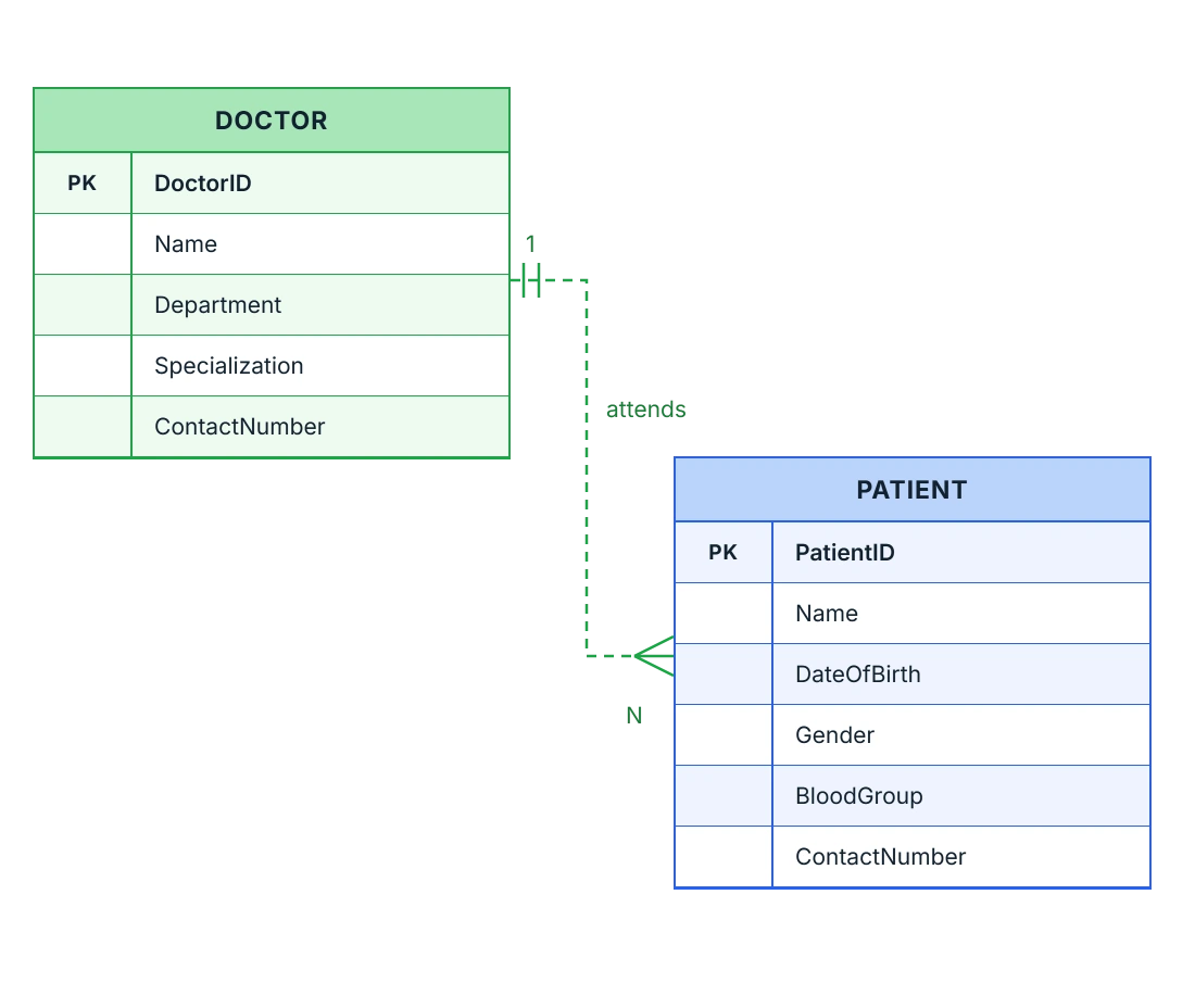
A relationship between two entities is drawn with a dedicated connector type that renders standard Crow’s Foot symbols at each end, rather than plain lines with text labels. Use a relationship connector when the cardinality between two entities needs to be shown in standard notation.
- Support cardinality set independently at the source and target end of a relationship
- Provide cardinality types including one, one-and-only-one, many, zero-or-one, one-or-many, and zero-or-many
- Enable a relationship to be marked as identifying or non-identifying
- Allow attachment to a specific field using ports rather than the entity as a whole; see Connectors & Ports
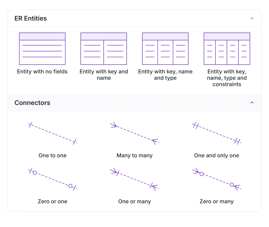
Built-in ER shapes in the symbol palette
Entity and relationship shapes don’t need to be assembled field by field. The symbol palette includes a set of predefined ER entities and connectors ready to drag onto the diagram. Use the symbol palette when ER shapes need to be assembled through drag-and-drop rather than programmatic configuration.
- Provide predefined entity layouts in the ER entities group, from a single column of fields to multiple side-by-side columns
- Deliver predefined cardinality combinations in the connectors group, ready to link two entities without setting each end separately
- Enable dragging a predefined entity or connector onto the canvas to start from a working example instead of an empty shape
- Support general symbol palette configuration as covered in Symbol Palette
PLATFORM SUPPORT
Entity relationship diagram support by platform
A dedicated entity and relationship shape system is confirmed through official documentation for React. JavaScript, Angular, and Vue share the same underlying diagram engine as React, so the same shapes are very likely available there as well, though a dedicated documentation page for each was not directly found. Blazor does not yet have this feature; it appears as an open, unresolved request in Syncfusion’s own feedback portal. Support on the remaining platforms is unconfirmed.
| Capability | JavaScript frameworks | ASP.NET Core and MVC | Blazor | WPF | UWP | Windows Forms |
|---|---|---|---|---|---|---|
| Dedicated entity and relationship shapes | ||||||
| Field data types and constraints | ||||||
| Runtime field add, remove, and change tracking | ||||||
| Crow's Foot cardinality on relationships | ||||||
| Built-in ER entities and connectors in a symbol palette |
Frequently Asked Questions
Does the Diagram SDK have a dedicated entity relationship shape type?
Yes, on platforms where it’s supported. A dedicated entity shape and a matching relationship connector render the header, fields, keys, and cardinality automatically; see the platform table above for availability. Where it isn’t yet available, an entity can still be approximated using custom node templates and standard connectors; see Diagram Elements.
Can fields be added to or removed from an entity after the diagram is built?
Yes, on platforms with runtime field support. A field can be added at a specific position or removed from an existing entity without recreating it, and a change event reports when fields are added, removed, or reordered.
Can a connector attach to a specific field instead of the whole entity?
Yes, using a port on that specific field rather than connecting to the entity shape as a whole. See Connectors & Ports for how ports work.
Is entity relationship diagram support identical across every platform?
No. A dedicated shape system is confirmed for React, is very likely available on JavaScript, Angular, and Vue since they share the same engine, and is not yet available for Blazor, which has an open feature request for it. Support on ASP.NET Core, ASP.NET MVC, WPF, UWP, and Windows Forms is unconfirmed, as shown in the table above.
How is an entity’s structure, like its list of fields, represented?
A dedicated entity shape displays a header naming the entity and its fields as rows beneath it, with each row showing that field’s name and data type.
How is cardinality shown on a relationship?
Through Crow’s Foot symbols rendered automatically at each end of a relationship connector. A cardinality type, such as one, many, or zero-or-many, is set independently for the source end and the target end.
Are ER entities and relationships available as predefined shapes to drag onto the canvas?
Yes, where symbol palette support for ER shapes is available. The palette includes several predefined entity layouts and several predefined connector cardinality combinations, ready to drag onto the diagram instead of configuring each one from scratch.
Resources
Learn more about our Diagram SDK
Explore demos, documentation, and support resources to get the most out of the Syncfusion Diagram SDK.
Review shared concepts and supported platforms
Representative ER diagram documentation
See entities, fields, keys, and cardinality in action
Ask, share, and connect with peers
Find solutions and best practices fast
Get expert help when needed
Feature requests and bug reports
Track issues and suggest improvements
Awards
Greatness—it’s one thing to say you have it, but it means more when others recognize it. Syncfusion® is proud to hold the following industry awards.