
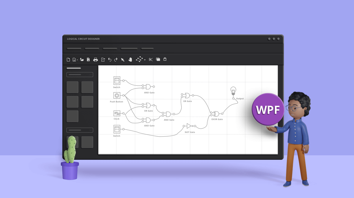
A well-crafted digital logic circuit can give clarity to a confusing system with clear visual representation and instruction on how to construct the physical digital logic circuit. Our WPF Diagram’s logic circuit designer is a handy diagram editor that allows you to design logic circuits easily.
In this blog post, we will walk you through designing logic circuits quickly and easily with an interactive user interface and the designer’s many useful features: drag and drop, copy, paste, import, export, pan, and zoom. Also, we will see the rich set of features available in our WPF Diagram to give your app a better user experience.
Logic circuit diagram symbols
The logic circuit designer provides a variety of universal logic gates, flip-flops, input controls, output controls, and other components to design logic circuit diagrams.
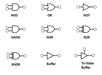
Logic gates
Logic gates are the basic symbols used for any digital circuit design. Logic gates perform Boolean logic functions with one or more inputs and produce a single output. The logic circuit designer has universal logic gates, including buffer and tri-state buffer.
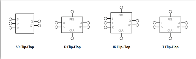
Flip-flops
A flip-flop is a circuit that has two stable states and can be used to store state information. The state can be changed by applying one or more control inputs and will have one or two outputs. It is the basic storage element in the digital circuit diagram. The logic circuit designer has SR, D, JK and T flip-flops for designing.
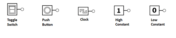
Input controls
Input controls can pass a high (true) or low (false) signal to logic gates or flip-flops. The logic circuit designer provides the following input controls for designing circuits.
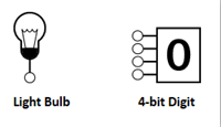
Output controls
Output controls can be connected to an output pin of a logic gate or flip-flop to display its output state. The logic circuit designer provides a light bulb and 8-bit digit as output controls.
Creating reusable logic circuit diagram symbols
The WPF Diagram control provides a gallery called stencil. This contains reusable symbols and diagram elements that can be dragged onto the diagram surface any number of times and in any place.
Let’s walk through the procedure to create a stencil with logic circuit diagram symbols. The stencil’s SymbolSource property is used to define the data source as a collection of objects (symbol, node, connector) that needs to be populated as symbols. The following code creates the stencil with logic gate symbols.
XAML
<stencil:Stencil x:Name="stencil"
FontWeight="Bold"
Grid.Row="1"
ExpandMode="OneOrMore"
SymbolFilters="{Binding Symbolfilters}" SelectedFilter="{Binding Selectedfilter}">
<stencil:Stencil.SymbolSource>
<Syncfusion:SymbolCollection>
<viewmodel:CustomNode Name="Buffer" UnitHeight="80" UnitWidth="100" ContentTemplate="{StaticResource BufferStencil}" Key="Logic Gates">
<!--Initialize the annotations-->
<Syncfusion:NodeViewModel.Annotations>
<!--Initialize the AnnotationCollection-->
<Syncfusion:AnnotationCollection>
<!--Initialize the Annotation editor view model-->
<Syncfusion:AnnotationEditorViewModel ReadOnly="True"/>
</Syncfusion:AnnotationCollection>
</Syncfusion:NodeViewModel.Annotations>
<Syncfusion:NodeViewModel.Ports>
<Syncfusion:PortCollection>
<Syncfusion:NodePortViewModel Constraints="InConnect" ConnectorPadding="6" Shape="{StaticResource OnPageReference}" NodeOffsetX="0.07" NodeOffsetY="0.48"/>
<Syncfusion:NodePortViewModel Constraints="OutConnect" ConnectorPadding="6" Shape="{StaticResource OnPageReference}" NodeOffsetX="0.93" NodeOffsetY="0.48"/>
</Syncfusion:PortCollection>
</Syncfusion:NodeViewModel.Ports>
</viewmodel:CustomNode>
<viewmodel:CustomNode Name="NOTGate" UnitHeight="80" UnitWidth="100" ContentTemplate="{StaticResource NOTGateStencil}" Key="Logic Gates">
<!--Initialize the annotations-->
<Syncfusion:NodeViewModel.Annotations>
<!--Initialize the AnnotationCollection-->
<Syncfusion:AnnotationCollection>
<!--Initialize the Annotation editor view model-->
<Syncfusion:AnnotationEditorViewModel ReadOnly="True"/>
</Syncfusion:AnnotationCollection>
</Syncfusion:NodeViewModel.Annotations>
<Syncfusion:NodeViewModel.Ports>
<Syncfusion:PortCollection>
<Syncfusion:NodePortViewModel Constraints="InConnect" ConnectorPadding="6" Shape="{StaticResource OnPageReference}" NodeOffsetX="0.07" NodeOffsetY="0.48"/>
<Syncfusion:NodePortViewModel Constraints="OutConnect" ConnectorPadding="6" Shape="{StaticResource OnPageReference}" NodeOffsetX="0.93" NodeOffsetY="0.48"/>
</Syncfusion:PortCollection>
</Syncfusion:NodeViewModel.Ports>
</viewmodel:CustomNode>
<viewmodel:CustomNode Name="ANDGate" UnitHeight="80" UnitWidth="100" ContentTemplate="{StaticResource ANDGateStencil}" Key="Logic Gates">
<!--Initialize the annotations-->
<Syncfusion:NodeViewModel.Annotations>
<!--Initialize the AnnotationCollection-->
<Syncfusion:AnnotationCollection>
<!--Initialize the Annotation editor view model-->
<Syncfusion:AnnotationEditorViewModel ReadOnly="True"/>
</Syncfusion:AnnotationCollection>
</Syncfusion:NodeViewModel.Annotations>
<Syncfusion:NodeViewModel.Ports>
<Syncfusion:PortCollection>
<Syncfusion:NodePortViewModel Constraints="InConnect" ConnectorPadding="6" Shape="{StaticResource OnPageReference}" NodeOffsetX="0.07" NodeOffsetY="0.28"/>
<Syncfusion:NodePortViewModel Constraints="InConnect" ConnectorPadding="6" Shape="{StaticResource OnPageReference}" NodeOffsetX="0.07" NodeOffsetY="0.75"/>
<Syncfusion:NodePortViewModel Constraints="OutConnect" ConnectorPadding="6" Shape="{StaticResource OnPageReference}" NodeOffsetX="0.93" NodeOffsetY="0.49"/>
</Syncfusion:PortCollection>
</Syncfusion:NodeViewModel.Ports>
</viewmodel:CustomNode>
<viewmodel:CustomNode Name="NANDGate" UnitHeight="80" UnitWidth="100" ContentTemplate="{StaticResource NANDGateStencil}" Key="Logic Gates">
<!--Initialize the annotations-->
<Syncfusion:NodeViewModel.Annotations>
<!--Initialize the AnnotationCollection-->
<Syncfusion:AnnotationCollection>
<!--Initialize the Annotation editor view model-->
<Syncfusion:AnnotationEditorViewModel ReadOnly="True"/>
</Syncfusion:AnnotationCollection>
</Syncfusion:NodeViewModel.Annotations>
<Syncfusion:NodeViewModel.Ports>
<Syncfusion:PortCollection>
<Syncfusion:NodePortViewModel Constraints="InConnect" ConnectorPadding="6" Shape="{StaticResource OnPageReference}" NodeOffsetX="0.07" NodeOffsetY="0.28"/>
<Syncfusion:NodePortViewModel Constraints="InConnect" ConnectorPadding="6" Shape="{StaticResource OnPageReference}" NodeOffsetX="0.07" NodeOffsetY="0.75"/>
<Syncfusion:NodePortViewModel Constraints="OutConnect" ConnectorPadding="6" Shape="{StaticResource OnPageReference}" NodeOffsetX="0.92" NodeOffsetY="0.49"/>
</Syncfusion:PortCollection>
</Syncfusion:NodeViewModel.Ports>
</viewmodel:CustomNode>
<viewmodel:CustomNode Name="ORGate" UnitHeight="80" UnitWidth="100" ContentTemplate="{StaticResource ORGateStencil}" Key="Logic Gates">
<!--Initialize the annotations-->
<Syncfusion:NodeViewModel.Annotations>
<!--Initialize the AnnotationCollection-->
<Syncfusion:AnnotationCollection>
<!--Initialize the Annotation editor view model-->
<Syncfusion:AnnotationEditorViewModel ReadOnly="True"/>
</Syncfusion:AnnotationCollection>
</Syncfusion:NodeViewModel.Annotations>
<Syncfusion:NodeViewModel.Ports>
<Syncfusion:PortCollection>
<Syncfusion:NodePortViewModel Constraints="InConnect" ConnectorPadding="6" Shape="{StaticResource OnPageReference}" NodeOffsetX="0.07" NodeOffsetY="0.28"/>
<Syncfusion:NodePortViewModel Constraints="InConnect" ConnectorPadding="6" Shape="{StaticResource OnPageReference}" NodeOffsetX="0.07" NodeOffsetY="0.75"/>
<Syncfusion:NodePortViewModel Constraints="OutConnect" ConnectorPadding="6" Shape="{StaticResource OnPageReference}" NodeOffsetX="0.93" NodeOffsetY="0.49"/>
</Syncfusion:PortCollection>
</Syncfusion:NodeViewModel.Ports>
</viewmodel:CustomNode>
<viewmodel:CustomNode Name="NORGate" UnitHeight="80" UnitWidth="100" ContentTemplate="{StaticResource NORGateStencil}" Key="Logic Gates">
<!--Initialize the annotations-->
<Syncfusion:NodeViewModel.Annotations>
<!--Initialize the AnnotationCollection-->
<Syncfusion:AnnotationCollection>
<!--Initialize the Annotation editor view model-->
<Syncfusion:AnnotationEditorViewModel ReadOnly="True"/>
</Syncfusion:AnnotationCollection>
</Syncfusion:NodeViewModel.Annotations>
<Syncfusion:NodeViewModel.Ports>
<Syncfusion:PortCollection>
<Syncfusion:NodePortViewModel Constraints="InConnect" ConnectorPadding="6" Shape="{StaticResource OnPageReference}" NodeOffsetX="0.07" NodeOffsetY="0.28"/>
<Syncfusion:NodePortViewModel Constraints="InConnect" ConnectorPadding="6" Shape="{StaticResource OnPageReference}" NodeOffsetX="0.07" NodeOffsetY="0.75"/>
<Syncfusion:NodePortViewModel Constraints="OutConnect" ConnectorPadding="6" Shape="{StaticResource OnPageReference}" NodeOffsetX="0.93" NodeOffsetY="0.49"/>
</Syncfusion:PortCollection>
</Syncfusion:NodeViewModel.Ports>
</viewmodel:CustomNode>
<viewmodel:CustomNode Name="XORGate" UnitHeight="80" UnitWidth="100" ContentTemplate="{StaticResource XORGateStencil}" Key="Logic Gates">
<!--Initialize the annotations-->
<Syncfusion:NodeViewModel.Annotations>
<!--Initialize the AnnotationCollection-->
<Syncfusion:AnnotationCollection>
<!--Initialize the Annotation editor view model-->
<Syncfusion:AnnotationEditorViewModel ReadOnly="True"/>
</Syncfusion:AnnotationCollection>
</Syncfusion:NodeViewModel.Annotations>
<Syncfusion:NodeViewModel.Ports>
<Syncfusion:PortCollection>
<Syncfusion:NodePortViewModel Constraints="InConnect" ConnectorPadding="6" Shape="{StaticResource OnPageReference}" NodeOffsetX="0.07" NodeOffsetY="0.28"/>
<Syncfusion:NodePortViewModel Constraints="InConnect" ConnectorPadding="6" Shape="{StaticResource OnPageReference}" NodeOffsetX="0.07" NodeOffsetY="0.75"/>
<Syncfusion:NodePortViewModel Constraints="OutConnect" ConnectorPadding="6" Shape="{StaticResource OnPageReference}" NodeOffsetX="0.92" NodeOffsetY="0.51"/>
</Syncfusion:PortCollection>
</Syncfusion:NodeViewModel.Ports>
</viewmodel:CustomNode>
<viewmodel:CustomNode Name="XNORGate" UnitHeight="80" UnitWidth="100" ContentTemplate="{StaticResource XNORGateStencil}" Key="Logic Gates">
<!--Initialize the annotations-->
<Syncfusion:NodeViewModel.Annotations>
<!--Initialize the AnnotationCollection-->
<Syncfusion:AnnotationCollection>
<!--Initialize the Annotation editor view model-->
<Syncfusion:AnnotationEditorViewModel ReadOnly="True"/>
</Syncfusion:AnnotationCollection>
</Syncfusion:NodeViewModel.Annotations>
<Syncfusion:NodeViewModel.Ports>
<Syncfusion:PortCollection>
<Syncfusion:NodePortViewModel Constraints="InConnect" ConnectorPadding="6" Shape="{StaticResource OnPageReference}" NodeOffsetX="0.07" NodeOffsetY="0.28"/>
<Syncfusion:NodePortViewModel Constraints="InConnect" ConnectorPadding="6" Shape="{StaticResource OnPageReference}" NodeOffsetX="0.07" NodeOffsetY="0.75"/>
<Syncfusion:NodePortViewModel Constraints="OutConnect" ConnectorPadding="6" Shape="{StaticResource OnPageReference}" NodeOffsetX="0.93" NodeOffsetY="0.51"/>
</Syncfusion:PortCollection>
</Syncfusion:NodeViewModel.Ports>
</viewmodel:CustomNode>
<viewmodel:CustomNode Name="Tri-State" UnitHeight="80" UnitWidth="100" ContentTemplate="{StaticResource Tri-StateStencil}" Key="Logic Gates">
<!--Initialize the annotations-->
<Syncfusion:NodeViewModel.Annotations>
<!--Initialize the AnnotationCollection-->
<Syncfusion:AnnotationCollection>
<!--Initialize the Annotation editor view model-->
<Syncfusion:AnnotationEditorViewModel ReadOnly="True"/>
</Syncfusion:AnnotationCollection>
</Syncfusion:NodeViewModel.Annotations>
<Syncfusion:NodeViewModel.Ports>
<Syncfusion:PortCollection>
<Syncfusion:NodePortViewModel Constraints="InConnect" ConnectorPadding="6" Shape="{StaticResource OnPageReference}" NodeOffsetX="0.49" NodeOffsetY="0.13"/>
<Syncfusion:NodePortViewModel Constraints="InConnect" ConnectorPadding="6" Shape="{StaticResource OnPageReference}" NodeOffsetX="0.08" NodeOffsetY="0.68"/>
<Syncfusion:NodePortViewModel Constraints="OutConnect" ConnectorPadding="6" Shape="{StaticResource OnPageReference}" NodeOffsetX="0.93" NodeOffsetY="0.69"/>
</Syncfusion:PortCollection>
</Syncfusion:NodeViewModel.Ports>
</viewmodel:CustomNode>
</Syncfusion:SymbolCollection>
</stencil:Stencil.SymbolSource>
<stencil:Stencil.SymbolGroups>
<stencil:SymbolGroups>
<!--Separate groups based on the key-->
<stencil:SymbolGroupProvider MappingName="Key"/>
</stencil:SymbolGroups>
</stencil:Stencil.SymbolGroups>
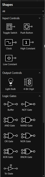
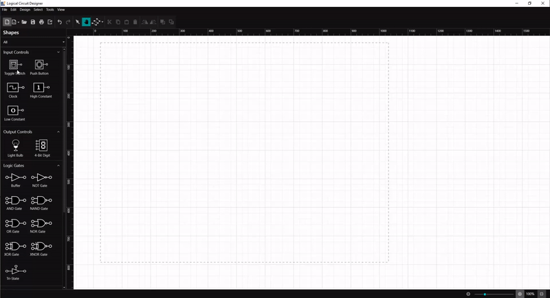
</stencil:Stencil>The following screenshot shows the collection of logic circuit diagram symbols in the created stencil.
You can refer to this stencil documentation page for details on adding symbols, grouping symbols, and customizing the stencil appearance.
Creating a diagram surface
Now, we have set up reusable logic circuit diagram shapes in our stencil. Let’s add the diagram surface to create our circuit designer environment with the following code example.
XAML
<Syncfusion:SfDiagram x:Name="Diagram" Grid.Column="1"
PortVisibility="{Binding PortVisibility}"
Nodes="{Binding Nodes}"
Connectors="{Binding Connectors}"
ScrollSettings="{Binding ScrollSettings}"
PageSettings="{Binding PageSettings}"
VerticalRuler="{Binding VerticalRuler}"
HorizontalRuler="{Binding HorizontalRuler}"
PrintingService="{Binding PrintingService}"
Constraints="{Binding Constraints}"
Tool="{Binding Tool}"
SelectedItems="{Binding SelectedItems}"
ExportSettings="{Binding ExportSettings}"
SnapSettings="{Binding SnapSettings}"
DragEnterCommand="{Binding DragEnterCommand}"
DragOverCommand="{Binding DragOverCommand}"
ItemAddedCommand="{Binding ItemAddedCommand}"
ItemSelectedCommand="{Binding ItemSelectedCommand}"
ItemUnSelectedCommand="{Binding ItemUnSelectedCommand}"
DropCommand="{Binding DropCommand}"
DefaultConnectorType="{Binding DefaultConnectorType}"
ViewPortChangedCommand="{Binding ViewPortChangedCommand}"
Loaded="Diagram_Loaded">
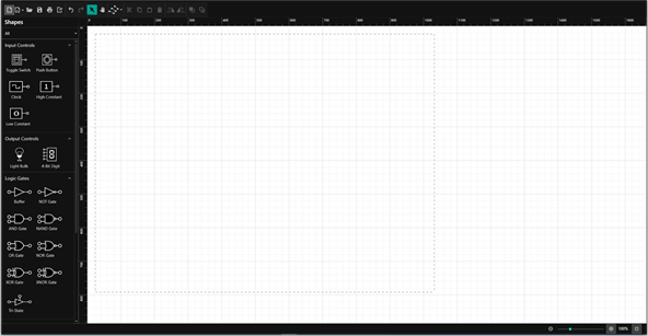
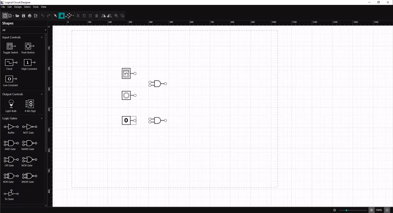
</Syncfusion:SfDiagram>The following screenshot shows the created diagram surface along with the logic circuit diagram symbols stencil.
You can refer to this Diagram documentation page for more details on how to add a diagram surface to your application and customize its appearance.
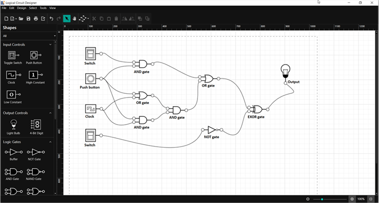
How to create a logic circuit diagram
You can design digital logic circuit diagrams by adding the symbols in the stencil to the diagram surface and connecting them using connectors.
Add symbols
Create the design by dragging the symbols from the stencil and dropping them onto the diagram surface at the desired locations.
Moving symbols
Change the position of the dropped symbols by simply clicking on the symbol to select it and dragging it to the desired location in the diagram surface.
Connect symbols
Each diagram symbol has input and output connection points (indicated by a small circle in the symbol) to connect the symbol with desired input and output controls as per our design. You can connect the output of one symbol as an input of another symbol.
To create the connection, hover the mouse over the connection point. You will see an animation to indicate the connection start or end point. Click it and start dragging the mouse to establish a connection.

You can refer to this documentation page for more details on adding connection points and creating connections.
Change line style
The WPF Diagram control provides three different types of connection lines: straight, orthogonal, and Bézier. You can change the connector line by selecting the connector and using the connector toolbar option or using the Tools->Connector menu option.

You can refer to the connector types documentation page for more details on different types of connectors and how to change the connector type in your application.
Loading and saving a diagram
The Diagram control provides the flexibility to save your current work and resume it by loading the saved diagram back into the diagram canvas. You can achieve this using the load and save functionality as illustrated.
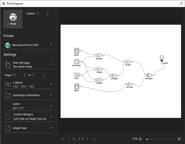
Print and export diagrams
You can export the created logic circuit diagram as an image, or you can print it directly using the printer. You can do this using the exporting and printing functionalities of the Diagram control.
The following screenshot shows the Print Diagram dialog box along with the custom print options.
Pan and zoom
The WPF Diagram control provides the support to zoom in or out in the diagram view. Zoom in or out using Ctrl and the mouse wheel or using the slider at the bottom-right corner of the designer.
When a large diagram is loaded, only a certain portion of it will be visible. The remaining portions will be clipped. Clipped portions can be explored by scrolling with the scrollbars or panning. You can pan the diagram by selecting the panning tool in the toolbar or Tools->Pan menu and then clicking the mouse in the diagram area and moving it without releasing the mouse click.

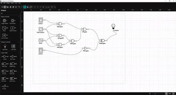
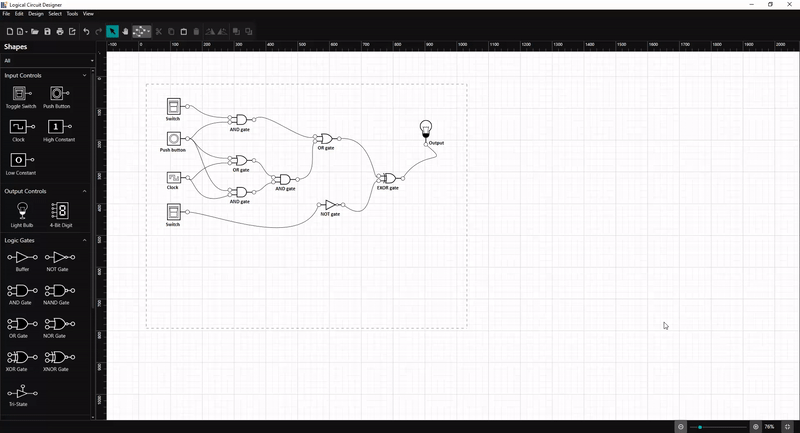
Logic circuit diagram examples
The logic circuit designer provides some examples of circuit diagrams. You can load them using the following highlighted button in the toolbar.
![]()
Click on any logic circuit diagram included in logic circuit designer and edit it.
Resource
You can download this logic circuit designer source project from this GitHub location.
Conclusion
In this blog post, we have seen the procedure to create a logic circuit diagram easily using our logic circuit diagram application. Also, we have learned to load, save, export, and print the created logic circuit diagram using the Syncfusion WPF Diagram library.
Similarly, you can create your own diagram creation application like an organization chart creator, a flow chart creator, or a network diagram. Syncfusion WPF Diagram library has rich, interactive features; automatic layouts; and data binding for different data sources. To explore its features in more depth, refer to our help documentation on the WPF Diagram library.
If you’re already a Syncfusion user, you can download the product setup from our website. If not, you can download a free, 30-day trial here.
If you have any questions, please let us know in the comments section below. You can also contact us through our support forum, Direct-Trac, or feedback portal. We are always happy to assist you!


 No spam, just valuable updates.
Comments (4)
Will be released for xamarin forms?
Hi Junior Oliveira,
We have support for SfDiagram control in Xamarin.Forms platform. Please refer to the following link to know the rich set of features available in our Xamarin.Forms SfDiagram control,
https://www.syncfusion.com/xamarin-ui-controls/xamarin-diagram
Also please refer our UG documentation for more details,
https://help.syncfusion.com/xamarin/diagram/overview
Regards,
Sarath
Hi, is it possible to build a logical combinational circuit from a logical expression with WPF ?
Hi Sarah,
Yes, it is possible. Please refer the below sample where we have implemented logical expression for AND and OR gates. Similarly, you can build a logical combinational circuit from a logical expression using other gates as well.
https://github.com/SyncfusionExamples/WPF-Diagram-Examples/tree/master/Samples/LogicCircuit/LogicCircuitSimulation
Regards,
Sarath