

Providing coordinates to every element in the creation of a flowchart is tedious. To help you avoid this tiresome process, the Syncfusion WPF Diagram library does it with just a few configuration settings. In this blog, I will walk you through the creation of a flowchart using the Syncfusion Diagram library without manually specifying coordinates, and instead using the built-in flowchart automatic layout algorithm.
A flowchart is a diagrammatic representation of a process, workflow, system, or computer algorithm. Flowcharts use various symbols to illustrate different types of actions and these symbols are connected by arrows showing the flow direction of the process.
Common flowchart symbols
Different flowchart symbols have different meanings that are used to represent specific states in a flowchart. The following table describes the most common flowchart symbols.
| Symbol | Name | Description |
 |
Terminator/Start/End | Indicates the beginning or end of a process. |
 |
Data | Indicates data input or output for a process. |
 |
Process | Represents an operation or set of operations and data manipulations. |
 |
Decision | Shows a branching point where a decision is made to choose one of two paths. |
 |
Document | Represents a single document or report in the process. |
 |
Subprocess/Predefined process | Represents a sequence of actions that combine to perform a specific task that is defined elsewhere. |
 |
Database | Represents a collection of information that allows for searching, sorting, and filtering. |
 |
Data storage | Represents a step where data is stored within a process. |
 |
Manual input | Represents the manual input of data into a field or step in a process. |
 |
Manual operation | Represents an operation in a process that must be done manually, not automatically. |
 |
Preparation | Represents a setup or initialization process for another step in the process. |
 |
On-page reference | Represents a pair of labeled connectors used to link long or confusing lines in a flowchart. |
 |
Off-page reference | Represents a labeled connector used to link two flowcharts on different pages. |
 |
Multidocument | Represents multiple documents or reports in a process. |
| Flowline | Represents a direction of flow from one step to another. |
Getting started with a simple flowchart
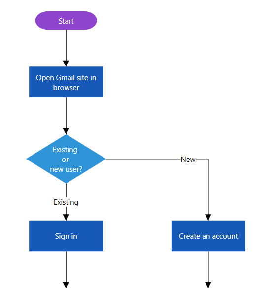
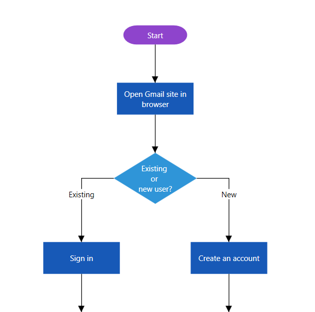
Let’s create a simple flowchart like the one shown in the following image using the Syncfusion Diagram library. The Diagram control has a built-in high-performance layout algorithm to arrange every flowchart symbol automatically, and it supports visualizing a flowchart from a data source.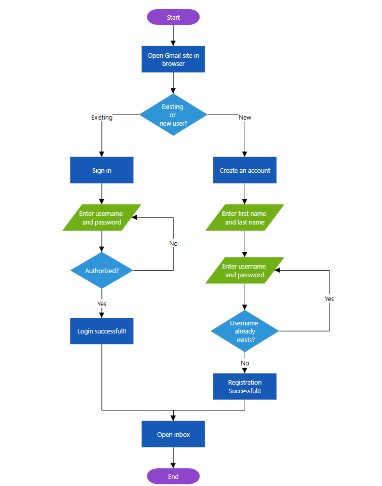
Flowchart Built with the Diagram Control’s Automatic Layout Algorithm
- Create a WPF application and refer to our help documentation to learn more about the dependent assembly references and namespaces required to integrate the Diagram control.
- Define the flowchart information as a data source. The information should contain the flowchart symbol shape data, a short description about each action, and the symbol width and height.
- Create an instance of the Diagram control.
- Create an instance of FlowchartDataSourceSettings with the data mapping configuration and assign it to the DataSourceSettings property of the created Diagram instance.
- Configure the LayoutManager with flowchart layout settings to arrange the flowchart elements automatically. The settings will configure the flowchart orientation, horizontal and vertical spacing between symbols, and decision output branch directions.
In the Diagram control, the different shapes shown in the previous screenshot represent nodes, and lines represent connectors. The text inside the shapes and lines represent annotations. The following code example includes all the previous steps. The complete sample is available from the Syncfusion website.
/// <summary>
/// Interaction logic for MainWindow.xaml
/// </summary>
public partial class MainWindow : Window
{
    public MainWindow()
    {
        InitializeComponent();
        //Initialize new instance of Diagram control
        SfDiagram diagram = new SfDiagram();
        //Initialize Nodes with Observable Collection of NodeViewModel.
        diagram.Nodes = new NodeCollection();
        //Initialize Connectors with Observable Collection of ConnectorViewModel
        diagram.Connectors = new ConnectorCollection();
        RootGrid.Children.Add(diagram);
        // Initialize DataSourceSettings for SfDiagram
        diagram.DataSourceSettings = new FlowchartDataSourceSettings()
        {
            //Set the unique field from data source
            Id = "Id",
            //Field used to identify the previous flowchart element
            ParentId = "ParentId",
            //Define the flowchart information
            DataSource = GetData(),
            //Field used to identify the line text
            ConnectorTextMapping = "LineText",
            //Field used to identify the symbol description
            ContentMapping = "Description",
            //Field used to identify the symbol shape
            ShapeMapping = "Shape",
            //Field used to identify the symbol width
            WidthMapping = "Width",
            //Field used to identify the symbol height
            HeightMapping = "Height"
        };

        // Initialize LayoutSettings for SfDiagram
        diagram.LayoutManager = new LayoutManager()
        {
            Layout = new FlowchartLayout()
            {
                //Set the flowchart flow direction
                Orientation = FlowchartOrientation.TopToBottom,
                //Set the decision yes branch direction
                YesBranchDirection = BranchDirection.LeftInFlow,
                //Set the decision no branch direction
                NoBranchDirection = BranchDirection.RightInFlow,
                //Set the custom yes branch values
                YesBranchValues = new List<string> { "Yes", "Existing" },
                //Set the custom no branch values
                NoBranchValues = new List<string> { "No", "New" },
                //Set the horizontal spacing between node
                HorizontalSpacing = 60,
                //Set the vertical spacing between node
                VerticalSpacing = 40,
                Margin = new Thickness(10),
            },
        };
    }
    /// <summary>
    /// Method to Get Data for DataSource
    /// </summary>
    /// <param name="data"></param>
    private SymbolInfoCollection GetData()
    {
        SymbolInfoCollection symbolInfoCollection = new SymbolInfoCollection();
        #region Gmail
        symbolInfoCollection.Add(new SymbolInfo() { Id = "1", Description = "Start", Shape = App.Current.Resources["StartOrEnd"] as string, Width = 100, Height = 30, Color = "#8E44CC" });

        symbolInfoCollection.Add(new SymbolInfo() { Id = "2", Description = "Open Gmail site in browser", ParentId = new List<string> { "1" }, Shape = App.Current.Resources["Rectangle"] as string, Width = 120, Height = 50, Color = "#1759B7" });

        symbolInfoCollection.Add(new SymbolInfo() { Id = "3", Description = "Existing \nor \nnew user?", ParentId = new List<string> { "2" }, Shape = App.Current.Resources["Decision"] as string, Width = 130, Height = 80, Color = "#2F95D8" });

        symbolInfoCollection.Add(new SymbolInfo() { Id = "4", LineText = new List<string> { "New" }, Description = "Create an account", ParentId = new List<string> { "3" }, Shape = App.Current.Resources["Rectangle"] as string, Width = 120, Height = 50, Color = "#1759B7" });

        symbolInfoCollection.Add(new SymbolInfo() { Id = "5", Description = "Sign in", LineText = new List<string> { "Existing" }, ParentId = new List<string> { "3" }, Shape = App.Current.Resources["Rectangle"] as string, Width = 120, Height = 50, Color = "#1759B7" });

        symbolInfoCollection.Add(new SymbolInfo() { Id = "6", Description = "Enter username \nand password", LineText = new List<string> { "", "No" }, ParentId = new List<string> { "5", "7" }, Shape = App.Current.Resources["Data"] as string, Width = 150, Height = 50, Color = "#70AF16" });

        symbolInfoCollection.Add(new SymbolInfo() { Id = "7", Description = "Authorized?", ParentId = new List<string> { "6" }, Shape = App.Current.Resources["Decision"] as string, Width = 120, Height = 70, Color = "#2F95D8" });

        symbolInfoCollection.Add(new SymbolInfo() { Id = "8", Description = "Login successful!!", LineText = new List<string> { "Yes" }, ParentId = new List<string> { "7" }, Shape = App.Current.Resources["Rectangle"] as string, Width = 120, Height = 50, Color = "#1759B7" });

        symbolInfoCollection.Add(new SymbolInfo() { Id = "9", Description = "Enter first name \nand last name", ParentId = new List<string> { "4" }, Shape = App.Current.Resources["Data"] as string, Width = 150, Height = 50, Color = "#70AF16" });

        symbolInfoCollection.Add(new SymbolInfo() { Id = "10", Description = "Enter username \nand password", LineText = new List<string> { "", "Yes" }, ParentId = new List<string> { "9", "11" }, Shape = App.Current.Resources["Data"] as string, Width = 150, Height = 50, Color = "#70AF16" });

        symbolInfoCollection.Add(new SymbolInfo() { Id = "11", Description = "Username \nalready\n exists?", ParentId = new List<string> { "10" }, Shape = App.Current.Resources["Decision"] as string, Width = 130, Height = 80, Color = "#2F95D8" });

        symbolInfoCollection.Add(new SymbolInfo() { Id = "12", Description = "Registration Successful!!", LineText = new List<string> { "No" }, ParentId = new List<string> { "11" }, Shape = App.Current.Resources["Process"] as string, Width = 120, Height = 50, Color = "#1759B7" });

        symbolInfoCollection.Add(new SymbolInfo() { Id = "13", Description = "Open inbox", ParentId = new List<string> { "8", "12" }, Shape = App.Current.Resources["Process"] as string, Width = 120, Height = 50, Color = "#1759B7" });

        symbolInfoCollection.Add(new SymbolInfo() { Id = "14", Description = "End", ParentId = new List<string> { "13" }, Shape = App.Current.Resources["StartOrEnd"] as string, Width = 100, Height = 30, Color = "#8E44CC" });
        #endregion

        return symbolInfoCollection;
    }
}
Features
Flowchart orientation customization
You can customize the flowchart orientation to be vertical (from top to bottom) or horizontal (from left to right).
Use the Orientation property of the FlowchartLayout class to define the flow direction either as TopToBottom or LeftToRight. Refer to the following code example for details.
LayoutManager = new LayoutManager()
{
    Layout = new FlowchartLayout()
    {
        //Set the flowchart flow direction
        Orientation = FlowchartOrientation.LeftToRight
    },
};
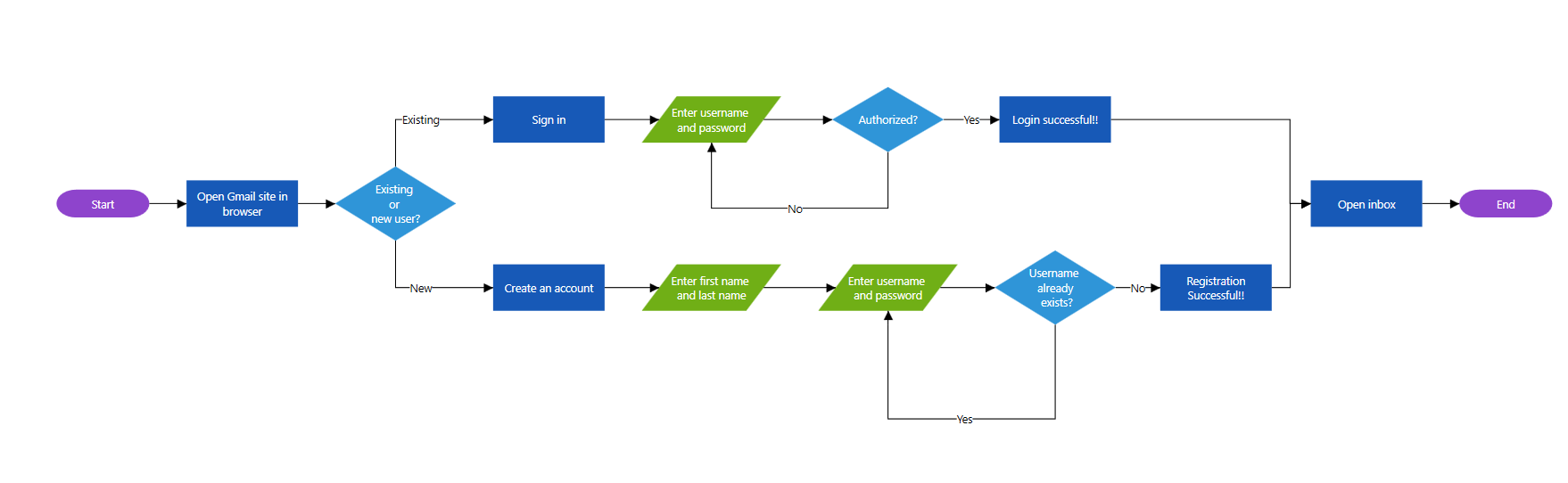
Horizontal Flowchart
Customize the decision symbol output directions
The decision symbol shows a branching point where a decision is made to choose one of two paths. The YesBranchDirection and NoBranchDirection properties of FlowchartLayout controls the direction of the Yes and No branches. The following code example illustrates this.
LayoutManager = new LayoutManager()
{
    Layout = new FlowchartLayout()
    {
        //Set the decision yes branch direction
        YesBranchDirection = BranchDirection.SameAsFlow,
        //Set the decision no branch direction
        NoBranchDirection = BranchDirection.RightInFlow,
    },
};
Flowchart with Decision Branch
Customize Yes and No branch line text
The decision symbol will produce two branches as output: a Yes branch and a No branch. If the output branch connector text value matches the values in the YesBranchValues property of the FlowchartLayout class, it will be considered a Yes branch. Similarly, if a connector text value matches the values in the NoBranchValues property, it will be considered a No branch. By default, the YesBranchValues property will contain Yes and True string values and the NoBranchValues property will contain No and False string values.
Provide any text value to the connector text to describe the flow. Also, provide any string value in the YesBranchValues and NoBranchValues. To decide the flow based on if or else, the connector text should match the values in the YesBranchValues and NoBranchValues. The following code example illustrates this.
//Add the custom yes branch values
(LayoutManager.Layout as FlowchartLayout).YesBranchValues.Add("Existing");
//Add the custom no branch values
(LayoutManager.Layout as FlowchartLayout).NoBranchValues.Add("New");
Summary
In this blog post, we have seen how to create and customize flowcharts from data without specifying coordinates using the Syncfusion WPF Diagram library. You can also use the library to create an interactive flowchart maker application. More built-in automatic layouts, such as hierarchical and radial tree, are also available in the Diagram control. To explore more in-depth features, refer to our help documentation on automatic layouts.
If you’re already a Syncfusion user, you can download the product setup from our website. Otherwise, you can download a free, 30-day trial here.
If you have any questions, please let us know in the comments section below. You can also contact us through our support forum, Direct-Trac, or feedback portal. We are always happy to assist you!


 No spam, just valuable updates.