
Direct3D Succinctly®

CHAPTER 6
Texture Mapping
Models can be made to look much more realistic by applying a texture. A texture is a flat image file which is wrapped around a polygon. For instance, a model of a table could have a wooden texture applied to it, characters might have a skin and facial features textures applied, and the ground in a 3-D scene might have a grass texture.
The process of wrapping a 3-D model in a texture is called texture mapping. The mapping part of the term comes about because the 2-D image’s pixels must be mapped to their corresponding vertices in the 3-D model. Most models are more complex than basic rectangles, and 3-D modeling applications are usually used to generate the texture coordinates which map to the vertices.
Texel or UV Coordinates
A 2-D image is wrapped around a mesh to create the illusion of a complex colored object. The pixels in the 2-D image are usually referenced using what is called a texel, or UV coordinates. Instead of using X and Y, texel coordinates are described with U and V components. The U component is the same as X, in it represents the horizontal axis, and the V component is analogous to the Y-axis, representing the vertical axis. The main difference between UV coordinates and standard Cartesian XY coordinates is that UV coordinates reference positions in an image as normalized values between 0.0 and 1.0. The point (0.0, 0.0) references the top left corner of the image and (1.0, 1.0) references the lower right corner. Every point in the image has a UV coordinate between (0.0, 0.0) and (1.0, 1.0). Figure 6.1 is a grassy texture that could be applied to the ground of a video game. Several points in the texture have been highlighted to show what the UV values coordinates.
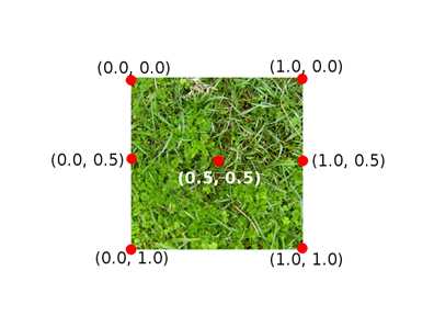
Figure 6.1: Texel/UV Coordinates
Texel coordinates do not reference particular pixels in the image; they are normalized positions. The GPU is very efficient at sampling pixels or collections of pixels referenced in this way. If a texture is very detailed, the texel coordinates may be read for multiple pixels in the texture and averaged for the final color on screen. Vice versa is also common; the texture may be small and lack separate colors for each pixel in the final image. In this case, the colors of the texture will be stretched over the faces to which the texture is mapped.
UV Layouts
It is easy to map a rectangular or square texture to a 3-D rectangle object, but mapping a 2-D texture to a mesh, like our spaceship from the previous chapter, is a little trickier. It is best to use the 3-D modeling application to export a UV layout from the mesh. The 3-D modeling software is also able to generate and export the UV coordinates that reference the layout. We saw these coordinates in the previous chapter’s object file code. I’ve used Blender to export the UV layout for our spaceship model pictured in Figure 6.2; this was the spaceship.png UV layout. The UV layout is a collection of the outlines of the faces from a model. We can paint these shapes using a standard 2-D image editor. These shapes are referenced in the spaceship.obj file as the VT coordinates.

Figure 6.2: Spaceship UV Layout
Each of the shapes in Figure 6.2 corresponds to a face in the spaceship. I have used Gimp 2.8.4 to create the textures in this book. Gimp is available from (http://www.gimp.org/). If you want to create your own texture for the spaceship, copy the above image into a 2-D image application such as Gimp and save it as spaceship.png. In Figure 6.3, I have colored the shapes using a blue metal texture.
Note: The textures in this book were exported as PNG image files. PNG is good because it uses lossless compression, so the textures will not be damaged by compression artifacts like a JPEG, but they are smaller than a standard Bitmap file. PNG also supports transparency. When you copy the images from the book you may find that the colors differ. For instance, the background may be black instead of transparent. The background is not mapped or referenced by the UV coordinates in the OBJ file, and it will not be visible.
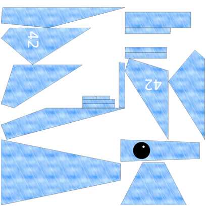
Figure 6.3: Textured UV Layout
In Figure 6.3, I have painted the UV with a blue steel texture. Copy and save the new textured UV layout from Figure 6.3 or create your own based on the UV layout in Figure 6.2. Once you have designed or saved the texture as spaceship.png, import the image into our Visual Studio project by right-clicking on the project name in the solution explorer, selecting Add Existing Item, and locating the PNG file.
Note: The original texture of Figure 6.3 was exported from Blender to a 1024x1024 PNG image. 2-D textures consume width*height*3 bytes of memory or width*height*4 with the alpha channel. A modest 128x128 or 256x256 PNG should be large enough to maintain detail in the texture and yet small enough so as not to consume all the memory of a portable device that is running the application. UV coordinates use percentages from 0.0 to 1.0 so textures can be scaled to suit the memory restrictions of the target device, and the UV coordinates referenced in the model’s mesh do not need to be changed.
Reading a Texture from a File
Now that we have added the PNG file to our project, we need to read the texture into our application and create an ID3D11Texture2D from it. This is the Direct3D object that represents a 2-D texture. We are using a standard PNG file, which Windows 8 has decoders for, so we can use the Windows Imaging Component (WIC) to read the file and turn it into an array of RGBA color values. We can then create the texture on the device from this array. We will wrap this functionality in a new class called Texture. Add two new files to the project, Texture.h and Texture.cpp. The code listings for this class are presented the following two code tables.
// Texture.h #pragma once #include <Windows.h> #include <string> #include "Model.h" using namespace DirectX; // This class reads an image from a file and creates an // ID3D11Texure2D and a ID3D11ShaderResourceView from it class Texture { Microsoft::WRL::ComPtr<ID3D11Texture2D> m_texture; Microsoft::WRL::ComPtr<ID3D11ShaderResourceView> m_resourceView; public: // Read a texture and create device resources void ReadTexture(ID3D11Device* device, IWICImagingFactory2* wicFactory, LPCWSTR filename);
// Getters Microsoft::WRL::ComPtr<ID3D11Texture2D> GetTexure() { return m_texture; } Microsoft::WRL::ComPtr<ID3D11ShaderResourceView> GetResourceView() { return m_resourceView; } }; |
// Texture.cpp.cpp #include "pch.h" #include "Texture.h" void Texture::ReadTexture(ID3D11Device* device, IWICImagingFactory2* wicFactory, LPCWSTR filename) { // Create a WIC decoder from the file IWICBitmapDecoder *pDecoder; DX::ThrowIfFailed(wicFactory->CreateDecoderFromFilename(filename, nullptr, GENERIC_READ, WICDecodeMetadataCacheOnDemand, &pDecoder)); // Create a frame, this will always be 0, PNG have only 1 frame IWICBitmapFrameDecode *pFrame = nullptr; DX::ThrowIfFailed(pDecoder->GetFrame(0, &pFrame)); // Convert the format to ensure it's 32bpp RGBA IWICFormatConverter *m_pConvertedSourceBitmap; DX::ThrowIfFailed(wicFactory->CreateFormatConverter(&m_pConvertedSourceBitmap)); DX::ThrowIfFailed(m_pConvertedSourceBitmap->Initialize( pFrame, GUID_WICPixelFormat32bppPRGBA, // Pre-multiplied RGBA WICBitmapDitherTypeNone, nullptr, 0.0f, WICBitmapPaletteTypeCustom)); // Create a texture2D from the decoded pixel data UINT width = 0; UINT height = 0; m_pConvertedSourceBitmap->GetSize(&width, &height); int totalBytes = width * height * 4; // Total bytes in the pixel data // Set up a rectangle which represents the size of the entire image: WICRect rect; rect.X = 0; rect.Y = 0; rect.Width = width; rect.Height = height; // Copy the entire decoded bitmap image to a buffer of bytes: BYTE *buffer = new BYTE[totalBytes]; DX::ThrowIfFailed(m_pConvertedSourceBitmap->CopyPixels(&rect, width * 4, totalBytes, buffer)); // Describe the texture we will create: D3D11_TEXTURE2D_DESC desc; ZeroMemory(&desc, sizeof(D3D11_TEXTURE2D_DESC)); desc.Width = width; desc.Height = height; desc.MipLevels = 1; desc.ArraySize = 1; desc.Format = DXGI_FORMAT_R8G8B8A8_UNORM; desc.SampleDesc.Count = 1; desc.SampleDesc.Quality = 0; desc.Usage = D3D11_USAGE_IMMUTABLE; desc.BindFlags = D3D11_BIND_SHADER_RESOURCE; desc.CPUAccessFlags = 0; desc.MiscFlags = 0; // Create the sub resource data which points to our BYTE *buffer D3D11_SUBRESOURCE_DATA subresourceData; ZeroMemory(&subresourceData, sizeof(D3D11_SUBRESOURCE_DATA)); subresourceData.pSysMem = buffer; subresourceData.SysMemPitch = (width * 4); subresourceData.SysMemSlicePitch = (width * height * 4); // Create the texture2d DX::ThrowIfFailed(device->CreateTexture2D(&desc, &subresourceData, m_texture.GetAddressOf())); // Create a resource view for the texture: D3D11_SHADER_RESOURCE_VIEW_DESC rvDesc; rvDesc.Format = desc.Format; // Use format from the texture rvDesc.ViewDimension = D3D11_SRV_DIMENSION_TEXTURE2D; // Resource is a 2D texture rvDesc.Texture2D.MostDetailedMip = 0; rvDesc.Texture2D.MipLevels = 1; // Create resource view: DX::ThrowIfFailed(device->CreateShaderResourceView( m_texture.Get(), &rvDesc, m_resourceView.GetAddressOf())); // Delete the WIC decoder pDecoder->Release(); pFrame->Release(); m_pConvertedSourceBitmap->Release(); // Delete the pixel buffer delete[] buffer; } |
The previous class uses the WIC decoders to read an image from a file. WIC decoders are able to read several common image formats. Once the decoder reads and decompresses the PNG image, the pixel data is copied to BYTE* buffer. We use a D3D11_TEXTURE2D_DESC structure to describe the texture being created, a D3D11_SUBRESOURCE_DATA structure to point to the texture’s pixel data in system memory, and then we create the texture using the device’s CreateTexture2D method. This will make a copy of the pixel data on the GPU. Once the pixel data is on the GPU, we do not need to maintain a copy in system RAM.
We also need to create an ID3D11ShaderResourceView. A resource can be made from multiple sub resources; an ID3D11ShaderResourceView is used to specify which sub resources can be used by the shaders and how the data in the resources is to be read.
Note: You will see references to MIP maps in the above previous code table. An MIP map, derived from the Latin “multum in parvo” or much in little, is a texture that is composed of the same texture at several levels of detail. MIP levels are used to improve performance. When the viewer of a 3-D object is very close to the object the most detailed texture can be applied, and when the viewer is far from the object a less detailed texture can be used. MIP maps are more advanced than what we are doing here, but they have a much better performance when rendering complex scenes.
Applying the Texture2D
We have loaded a model and we have a class to load the texture onto the GPU. We need to make some changes to the Model class and the Vertex structure to incorporate the new Vertex type with texture coordinates instead of colors. The Vertex structure in the Model.h file does not include texture coordinates; at the moment it’s just positions and colors. We do not need colors anymore since our new Vertex structure will include UV coordinates instead. The following code table highlights the changes in the Vertex structure. The old color element has been commented out, but this line can be replaced by the new one which defines the uv element for the structure.
// Definition of our vertex types struct Vertex { DirectX::XMFLOAT3 position; // DirectX::XMFLOAT3 color; DirectX::XMFLOAT2 uv; }; |
At the moment, our ModelReader is ignoring the vt texture coordinate specifications in the OBJ files it reads. Change the ModelReader.cpp file to read the texture coordinates. These changes have been highlighted in the following code table.
Model* ModelReader::ReadModel(ID3D11Device* device, char* filename) { // Read the file int filesize = 0; char* filedata = ReadFile(filename, filesize); // Parse the data into vertices and indices int startPos = 0; std::string line; // Vectors for vertex positions std::vector<float> vertices; std::vector<int> vertexIndices; // Vectors for texture coordinates std::vector<float> textureCoords; std::vector<int> textureIndices; int index; // The index within the line we're reading while(startPos < filesize) { line = ReadLine(filedata, filesize, startPos); if(line.data()[0] == 'v' && line.data()[1] == ' ') { index = 2; // Add to vertex buffer vertices.push_back(ReadFloat(line, index)); // Read X vertices.push_back(ReadFloat(line, index)); // Read Y vertices.push_back(ReadFloat(line, index)); // Read Z // If there's a "W" it will be ignored } else if(line.data()[0] == 'f' && line.data()[1] == ' ') { index = 2; // Add triangle to index buffer for(int i = 0; i < 3; i++) { // Read position of vertex vertexIndices.push_back(ReadInt(line, index)); // Read the texture coordinate textureIndices.push_back(ReadInt(line, index));
// Ignore the normals ReadInt(line, index ); } } else if(line.data()[0]=='v'&& line.data()[1] == 't' && line.data()[2] == ' ') { index = 3; // Add to texture textureCoords.push_back(ReadFloat(line, index)); // Read U textureCoords.push_back(ReadFloat(line, index)); // Read V } } // Deallocate the file data delete[] filedata; // Deallocate the file data // Subtract one from the vertex indices to change from base 1 // indexing to base 0: for(int i = 0; i < (int) vertexIndices.size(); i++) { vertexIndices[i]--; textureIndices[i]--; }
// Create a collection of Vertex structures from the faces std::vector<Vertex> verts; int j = vertexIndices.size(); int qq = vertices.size(); for(int i = 0; i < (int) vertexIndices.size(); i++) { Vertex v;
// Create a vertex from the referenced positions v.position = XMFLOAT3( vertices[vertexIndices[i]*3+0], vertices[vertexIndices[i]*3+1], vertices[vertexIndices[i]*3+2]); // Set the vertex's texture coordinates v.uv = XMFLOAT2( textureCoords[textureIndices[i]*2+0], 1.0f-textureCoords[textureIndices[i]*2+1] // Negate V ); verts.push_back(v); // Push to the verts vector } // Create a an array from the verts vector. // While we're running through the array reverse // the winding order of the vertices. Vertex* vertexArray = new Vertex[verts.size()]; for(int i = 0; i < (int) verts.size(); i+=3) { vertexArray[i] = verts[i+1]; vertexArray[i+1] = verts[i]; vertexArray[i+2] = verts[i+2]; } // Construct the model Model* model = new Model(device, vertexArray, verts.size()); // Clear the vectors vertices.clear(); vertexIndices.clear(); verts.clear(); textureCoords.clear(); textureIndices.clear(); // Delete the array/s delete[] vertexArray; return model; // Return the model } |
Next we can change the vertex and pixel shader HLSL files. The structure defined in these files should match the structure of new Vertex type with texture coordinates instead of colors. The altered code for these shaders is presented in the following code table for the vertex shader, and the second code table for the pixel shader.
// VertexShader.hlsl // The GPU version of the constant buffer cbuffer ModelViewProjectionConstantBuffer : register(b0) { matrix model; matrix view; matrix projection; }; // The input vertices struct VertexShaderInput { float3 position : POSITION; float2 tex : TEXCOORD0; }; // The output vertices as the pixel shader will get them struct VertexShaderOutput { float4 position : SV_POSITION; float2 tex : TEXCOORD0; }; // This is the main entry point to the shader: VertexShaderOutput main(VertexShaderInput input) { VertexShaderOutput output; float4 pos = float4(input.position, 1.0f); // Use constant buffer matrices to position the vertices: pos = mul(pos, model); // Position the model in the world pos = mul(pos, view); // Position the world with respect to a camera pos = mul(pos, projection);// Project the vertices output.position = pos; // Pass the texture coordinates unchanged to pixel shader output.tex = input.tex; return output; } |
// PixelShader.hlsl Texture2D shaderTexture; // This is the texture SamplerState samplerState; // Input is exactly the same as // vertex shader output! struct PixelShaderInput { float4 position : SV_POSITION; float2 tex: TEXCOORD0; }; // Main entry point to the shader float4 main(PixelShaderInput input) : SV_TARGET { float4 textureColor = shaderTexture.Sample(samplerState, input.tex); // Return the color unchanged return textureColor; } |
The vertex shader just passes the UV coordinates on to the pixel shader. The pixel shader requires some additional resources; it needs the texture (shaderTexture) and it needs a texture sampler state. I’ve called it samplerState. The pixel shader looks up the pixels in the texture using the Sample method. It passes the samplerState and the coordinate that is input.tex as parameters to this method. This method returns the color of the pixel, which the shader can then return. The pixel shader is still responsible for providing a color for each pixel. It now does so by sampling the texture in order to determine the color for each pixel.
Next, we need to load our texture from file and assign it to our Model, m_model. Add an include for the Texture.h header to the SimpleTextRenderer class in the SimpleTextRenderer.h file. The following code table shows the newly included file.
// SimpleTextRenderer.h #pragma once #include "DirectXBase.h" #include "Model.h" #include "VertexShader.h" #include "PixelShader.h" #include "ModelReader.h" #include "Texture.h" |
Add a member variable to this class; I have called mine m_texture in the code. The following code table highlights this modification in the SimpleTextRenderer.h file.
private: Model *m_model; Microsoft::WRL::ComPtr<ID3D11Buffer> m_constantBufferGPU; ModelViewProjectionConstantBuffer m_constantBufferCPU; Texture m_texture; // Shaders VertexShader m_vertexShader; PixelShader m_pixelShader; |
Textures are a device resource so they should be created in the SimpleTextRenderer::CreateDeviceResources method. Open the SimpleTextRenderer.cpp file and load the texture. I have placed this code directly after the m_model member variable is initialized. The following code table highlights the changes.
DirectXBase::CreateDeviceResources();
// Read the spaceship model m_model = ModelReader::ReadModel(m_d3dDevice.Get(), "spaceship.obj"); // Read the texture: m_texture.ReadTexture(m_d3dDevice.Get(), m_wicFactory.Get(), L"spaceship.png "); // Create the constant buffer on the device |
We also need to change our VertexShader class, since at the moment it is still expecting the data to contain COLOR values instead of TEXCOORD. Open the VertexShader.cpp file and alter the vertexDesc. These changes are highlighted in the following code table.
// Describe the layout of the data const D3D11_INPUT_ELEMENT_DESC vertexDesc[] = { { "POSITION", 0, DXGI_FORMAT_R32G32B32_FLOAT, 0, 0, D3D11_INPUT_PER_VERTEX_DATA, 0 }, { "TEXCOORD", 0, DXGI_FORMAT_R32G32_FLOAT, 0, 12, D3D11_INPUT_PER_VERTEX_DATA, 0 }, }; |
Make sure you make two changes here; the semantic name is TEXCOORD, but equally important is the fact that type is DXGI_FORMAT_R32G32_FLOAT, and there are now only two elements, not three.
Next we can create an ID3D11SamplerState member variable, m_samplerState. The sampler state is an object that holds information about the current sampler. First, add an m_samplerState member variable to the SimpleTextRenderer.h file. The declaration of the new member variable is highlighted in the code in the following code table.
private: Model *m_model; Microsoft::WRL::ComPtr<ID3D11Buffer> m_constantBufferGPU; ModelViewProjectionConstantBuffer m_constantBufferCPU; Texture m_texture; ID3D11SamplerState *m_samplerState; |
Note: According to Microsoft, you do not need to use a sampler state. There is a default state that will be assumed should the code not include its own. The problem is that some machines, including Windows RT Surface, do not seem to include any sampler state by default and if you do not specify a sampler state yourself, you might end up looking at a black, untextured model when debugging on some devices.
Sampler states are device resources. Open the SimpleTextRenderer.cpp file and create the sampler state at the end of the CreateDeviceResources method. The additional code is highlighted in the following code table.
// Load the shaders from files (note the CSO extension, not hlsl!): m_vertexShader.LoadFromFile(m_d3dDevice.Get(), "VertexShader.cso"); m_pixelShader.LoadFromFile(m_d3dDevice.Get(), "PixelShader.cso"); // Create the sampler state D3D11_SAMPLER_DESC samplerDesc; ZeroMemory(&samplerDesc, sizeof(D3D11_SAMPLER_DESC)); samplerDesc.Filter = D3D11_FILTER_MIN_MAG_MIP_LINEAR; samplerDesc.AddressU = D3D11_TEXTURE_ADDRESS_WRAP; samplerDesc.AddressV = D3D11_TEXTURE_ADDRESS_WRAP; samplerDesc.AddressW = D3D11_TEXTURE_ADDRESS_WRAP; samplerDesc.MipLODBias = 0.0f; samplerDesc.MaxAnisotropy = 1; samplerDesc.ComparisonFunc = D3D11_COMPARISON_ALWAYS; samplerDesc.BorderColor[0] = 0; samplerDesc.BorderColor[1] = 0; samplerDesc.BorderColor[2] = 0; samplerDesc.BorderColor[3] = 0; samplerDesc.MinLOD = 0; samplerDesc.MaxLOD = D3D11_FLOAT32_MAX; DX::ThrowIfFailed(m_d3dDevice->CreateSamplerState (&samplerDesc, &m_samplerState )); } |
Examining the previous code table should give a good idea of what a sampler state is. It is a way of specifying how a texture is to be read. The above sampler state specifies that we want linear interpolation (D3D11_FILTER_MIN_MAG_MIP_LINEAR); this will smooth the texture and make it appear less pixelated when viewing close up. We have also specified that the texture wraps round in every axis with the Addressxx settings. This means that the sampler sees the texture as an infinite, repeating, tiled pattern.
The next thing we need to do is set the resources for the shaders as active. Open the Render method in the SimpleTextRenderer.cpp file and call the m_d3dContext’s set methods with the resources we have just created. This tells the GPU which shaders and other resources are active. Once the GPU knows which vertices to render, which shaders to use, and which sampler state to use, we can render the model using the m_d3dContext’s Draw method. The following code table shows these changes to the Render method.
// Set the vertex buffer m_d3dContext->IASetVertexBuffers(0, 1, m_model->GetAddressOfVertexBuffer(), &stride, &offset);
// Set the sampler state for the pixel shader m_d3dContext->PSSetSamplers(0, 1, &m_samplerState); // Set the resource view which points to the texture m_d3dContext->PSSetShaderResources(0, 1, m_texture.GetResourceView().GetAddressOf()); // Render the vertices m_d3dContext->Draw(m_model->GetVertexCount(), 0); |
At this point you should be able to run the application and see an improved model spaceship, complete with the blue texture we painted earlier (Figure 6.4).
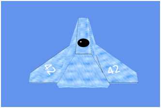
Figure 6.4: Textured Spaceship
- 1800+ high-performance UI components.
- Includes popular controls such as Grid, Chart, Scheduler, and more.
- 24x5 unlimited support by developers.