
Direct3D Succinctly®

CHAPTER 2
Introduction to 3-D Graphics
Before we dive into DirectX, it is important to look at some of the terms and concepts behind 3-D graphics. In this chapter, we will examine some fundamental concepts of 3-D graphics that are applicable to all graphics APIs.
3-D graphics is an optical illusion, or a collection of techniques for creating optical illusions. Colored pixels are lit up on a 2-D screen in such a way that the image on the screen resembles objects with perspective. Nearer objects overlap and block those farther away, just as they would in the real world.
Coordinate Systems
A coordinate system is a method for describing points in a geometric space. We will be using a standard Cartesian coordinate system for our 3-D graphics. In 2-D graphics, points are specified using two coordinates, one for each of the X and Y dimensions. The X coordinate usually specifies the horizontal location of a point, and the Y coordinate specifies the vertical location of a point. We will see later, when using 2-D textures, that it is also common to use the signifiers U and V to describe 2-D texture coordinates.
In 3-D space, points are specified using three coordinates (X, Y, and Z). Any two coordinates define a plane perpendicular to any other two. The positive and negative directions of each axis, with respect to the monitor, can be arbitrarily chosen by placing a virtual camera in the 3-D scene. For instance, the Y-axis can point upwards, the X-axis can point rightwards, and the Z-axis can point into the screen. If you rotate the camera, the Y-axis can point out of the screen, the X-axis can point downwards, and the Z-axis can point rightwards.
When working with a 3-D Cartesian coordinate system there is a choice to make as to which direction each of the axes point with respect to one another. Any two axes define a 2-D plane. For instance, the X- and Y-axes define a plane, and the Z- and X-axis define another. If you imagine a camera oriented in such a way that the X- and Y-axes define a plane parallel to the monitor, with the Y-axis pointing up and the X-axis pointing to the right, then there is a choice for which direction the Z-axis points. It can point into or out of the screen. A commonly used mnemonic for remembering these two coordinate systems is handedness, or right-handed coordinates and left-handed coordinates. When you hold your hands in the same manner as depicted in Figure 2.1, the fingers point in the positive directions of the axis.
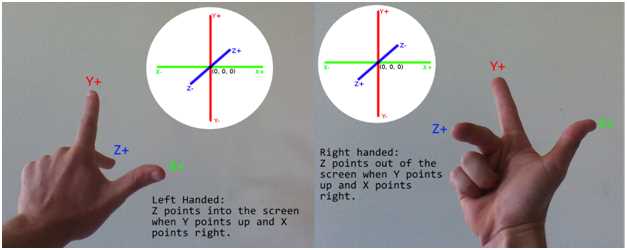
Figure 2.1: Left-handed and Right-handed Coordinates
When using a left-handed coordinate system, the positive Z-axis points into the screen, the Y-axis points up, and the X-axis points to the right. When using a right-handed coordinate system, the positive Z-axis points out of the screen, the Y points up, and the X points to the right. We will be using right-handed coordinates in the code, but DirectX is able to use either.
It is very important to know that the positive directions for the axes are only partially defined by the handedness of the coordinates. The positive directions for the axes can point in any direction with respect to the monitor, because the virtual camera or viewer is able to rotate upside down, backwards, or any direction.
Model, World, and View Space
Models are usually created as separate assets using a 3-D modeling application. I have used Blender for the examples in this book; Blender is available for download from http://www.blender.org/. Models can be exported from the modeling application to files and loaded into our programs. When the models are designed in the 3-D modeler, they are designed with their own local origin. For instance, if you designed a table model, it might look like Figure 2.2 in the modeling application.

Figure 2.2: Table in the Blender Modeler
Figure 2.2 is a cropped screen shot of the Blender workspace. The red and green lines intersect at the local origin for the object. In Blender, the red line is the X-axis and the green line is the Y-axis. The Z-axis is not pictured, but it would point upwards and intersect the same point that the X and Y intersect. The point where they meet is the location (0, 0, 0) in Blender's coordinates, it is the origin in model coordinates. When we export the object to a file that we can read into our application, the coordinates in the file will be specified with respect to the local origin.
Figure 2.3 shows another screen shot of the same model, but now it has been placed into a room.

Figure 2.3: Table in World Space
Once we load a model file into our application, we can place the object at any position in our 3-D world. It was modeled using its own local coordinates, but when we place it into the world, we do so by specifying its position relative to the origin of the world coordinates. The origin of the world coordinates can be seen in the image above. This is actually another screen shot from Blender, and usually the axis will not be visible. The table has been placed in a simple room with a floor, ceiling, and a few walls. This translation of the table's coordinates from its local coordinates to the world is achieved in DirectX using a matrix multiplication. We multiply the coordinates of the table by a matrix that positions the table in our 3-D world space. I will refer to this matrix as the model matrix, since it is used to position individual models.
Once the objects are positioned relative to the world origin, the final step in representing the world coordinate space is to place a camera or eye at some point in the virtual world. In 3-D graphics, cameras are positioned and given a direction to face. The camera sees an area in the virtual world that has a very particular shape. The shape is called a frustum. A frustum is the portion of a geometric shape, usually a pyramid or cone that lies between two parallel planes cutting the shape. The frustum in 3-D graphics is a square base pyramid shape with its apex at the camera. The pyramid is cut at the near and far clipping planes (Figure 2.4).

Figure 2.4: Frustum
Figure 2.4 depicts the viewing frustum. The camera is able to view objects within the yellow shaded frustum, but it cannot see objects outside this area. Objects that are closer to the camera than the blue shaded plane (called the near clipping plane) are not rendered, because they are too close to the camera. Likewise, objects that are beyond the orange shaded plane (called the far clipping plane) are also not rendered, because they are too far from the camera. The camera moves around the 3-D world, and any objects that fall in the viewing frustum are rendered. The objects that fall inside the viewing frustum are projected to the 2-D screen by multiplying by another matrix that is commonly called the projection matrix.
Figure 2.5 shows a representation of projecting a 3-D shape onto a 2-D plane. In DirectX, the actual process of projection is nothing more than a handful of matrix multiplications, but the illustration may help to conceptualize the operation.

Figure 2.5: 3-D Projection
Figure 2.5 illustrates 3-D projection onto a 2-D plane. The viewer of the scene, depicted as a camera, is on the left side of the image. The middle area, shaded in blue, is the projection plane. It is a plane, which means it is 2-D and flat. It represents the area that the viewer can see. On the far right side, we can see a 3-D cube. This is the object that the camera is looking at. The cube on the right is meant to be a real 3-D object, and the cube projected onto the plane is meant to be 2-D.
Colors
Each pixel on a monitor or screen has three tiny lights very close together. Every pixel has a red, green, and blue light, one beside the other. Each of these three lights can shine at different levels of intensity, and our eyes see a mixture of these three intensities as the pixel’s color. Humans see colors as a mixture of three primary colors: red, green, and blue.
Colors are described in Direct3D using normalized RGB or RGBA components. Each pixel has a red, green, and blue variable that specifies the intensity of each of the three primary colors. The components are normalized, so they should range from 0.0f to 1.0f inclusive. 0.0f means 0% of a particular component and 1.0f means 100%.
Colors are specified using three (RGB) or four (RGBA) floating point values with the red first, green second, and blue third. If there is an alpha component, it is last.
To create a red color with 100% red, 13% green and 25% blue, we can use (1.0f, 0.13f, 0.25f).

If present, the alpha component is normally used for transparency. In this book, we will not be using the alpha channel, and its value is irrelevant, but I will set it to 100% or 1.0f.
Graphics Pipeline
The graphics pipeline is a set of steps that take some representation of objects, usually a collection of 3-D coordinates, colors, and textures, and transform them into pixels to be displayed on the screen. Every graphics API has its own pipeline. For instance, the OpenGL pipeline is quite different from the DirectX graphics pipeline. The pipelines are always being updated, and new features are added with each new generation of the DirectX API.
In early versions of DirectX, the pipeline was fixed, and it was a predesigned set of stages that the programmers of the API designed. Programmers could select several options that altered the way the GPU rendered the final graphics, but the entire process was largely set in stone. Today's graphics pipeline is extremely flexible and it features many stages that are directly programmable. This means that the pipeline is vastly more complex, but it is also much more flexible. Figure 2.6 is a general outline of the stages of the current DirectX 11 graphics pipeline.

Figure 2.6: DirectX 11 Graphics Pipeline
The rectangular boxes in Figure 2.6 indicate stages that are necessary, and the ellipses indicate the stages that are optional. Purple stages are programmable using the HLSL language and blue boxes are fixed or nonprogrammable stages. The black arrows indicate the execution flow of the pipeline. For instance, the domain shader leads to the geometry shader, and the vertex shader has three possible subsequent stages. Following the vertex shader can be the hull shader, the geometry shader, or the pixel shader.
Each pipeline stage is designed to allow some specific functionality. In this book, we will concentrate on the two most important stages: the vertex shader stage and the pixel shader stage. The following is a general description of all the stages.
Input Assembler:
This stage of the pipeline reads data from the GPU's buffers and passes it to the vertex shader. It assembles the input for the vertex shader based on descriptions of the data and its layout.
Vertex Shader:
This stage processes vertices. It can lead to the hull, geometry, or pixel shader, depending on what the programmer needs to do. We will examine this stage in detail in later chapters. The vertex shader is a required stage, and it is also completely programmable using the HLSL language in DirectX.
Hull Shader:
This stage and the next two are all used for tessellation, and they are optional. Tessellation can be used to approximate complex shapes from simpler ones. The Hull shader creates geometry patches or control points for the tessellator stage.
Tessellator:
The tessellator takes the geometry patches from the hull shader and divides the primitives into smaller sections.
Domain Shader:
The domain shader takes the output from the tessellator and generates vertices from it.
Geometry Shader:
The geometry shader is a programmable part of the pipeline that works with entire primitives. These could be triangles, points, or lines. The geometry shader stage can follow the vertex shader if you are not using tessellation.
Rasterizer:
The rasterizer takes the output from the previous stages, which consists of vertices, and decides which are visible and which should be passed onto the pixel shaders. Any pixels that are not visible do not need to be processed by the subsequent pixel shader stage. A nonvisible pixel could be outside the screen or located on the back faces of objects that are not facing the camera.
Pixel Shader:
The pixel shader is another programmable part of the pipeline. It is executed once for every visible pixel in a scene. This stage is required, and we will examine pixel shaders in more detail in later chapters.
Output Merger:
This stage takes the output from the other stages and creates the final graphics.
Render Targets, Swap Chain, and the Back Buffer
The GPU writes pixel data to an array in its memory that is sent to the monitor for display. The memory buffer that the GPU writes pixels to is called a render target. There are usually two or more buffers; one is being shown on the screen, while the GPU writes the next frame to another that cannot be seen. The buffer the user can see is called the front buffer. The render target to which the GPU writes is called the back buffer. When the GPU has finished rendering a frame to the back buffer, the buffers swap. The back buffer becomes the front buffer and is displayed on the screen, and the front buffer becomes the back buffer. The GPU renders the next frame to the new back buffer, which was previously the front buffer. This repeated writing of data to the back buffer and swapping of buffers enables smooth graphics. These buffers are all 2-D arrays of RGB pixel data.
The buffers are rendered and swapped many times in sequence by an object called the swap chain. It is called a swap chain because there need not be only two buffers; there could be a chain of many buffers each rendered to and flipped to the screen in sequence.
Depth Buffer
When the GPU renders many objects, it must render those closer to the viewer and not the objects behind or obscured by these closer objects. It may seem that, if there are two objects one in front of the other, the viewer will see the front object and the hidden object does not need to be rendered. In graphics programming, the vertices and pixels are all rendered independently of each other using shaders. The GPU does not know when it is rendering a vertex if this particular vertex is in front of or behind all the other vertices in the scene.
We use a z-buffer to solve this problem. A z-buffer is a 2-D array usually consisting of floating point values. The values indicate the distance to the viewer from each of the pixels currently rasterized in the rasterizer stage of the pipeline. When the GPU renders a pixel from an object at some distance (Z) from the viewer, it first checks that the Z of the current pixel is closer than the Z that it previously rendered. If the pixel has already been rendered and the object was closer last time, the new pixel does not need to be rendered; otherwise the pixel should be updated.

Figure 2.7: Depth Buffer and Faces
Figure 2.7 illustrates two examples of a box being rasterized, or turned into pixels. There is a camera looking at the box on the left. In this example, we will step through rasterizing two faces of the boxes: the one nearest the camera and the one farthest away. In reality, a box has six faces, and this process should be easy to extrapolate to the remaining faces.
Imagine that, in example A, the first face of the box that is rasterized is described by the corners marked 1, 2, 3, and 4. This is the face nearest to the camera. The GPU will rasterize all the points on this face. It will record the distance from each point to the camera in the depth buffer as it writes the rasterized pixels to a pixel buffer.
Eventually, the farthest face from the camera will also be read. This face is described by the corners 5, 6, 7, and 8. Corner 8 is not visible in the diagram. Once again, the GPU will look at the points that comprise the face, and determine how far each is from the camera. It will look to the depth buffer and note that these points have already been rasterized. The distance that it previously recorded in the depth buffer is nearer to the camera than those from the far face. The points from the far face cannot be seen by the camera, because they are blocked by the front face. The pixels written while rasterizing the front face will not be overwritten.
Contrast this with example B on the right-hand side of Figure 2.7. Imagine that the face that is rasterized first is the one described by corners 1, 2, 3, and 4. Corner 4 is not depicted in the diagram. This time, it is the far face from the camera that is rasterized first. The GPU will determine the distance from each point on this face to the camera. It will write these distances to the depth buffer while writing the rasterized pixels to a pixel buffer. After a while, it will come to the nearer face, described by corners 5, 6, 7, and 8. The GPU will calculate the distance of each of the points on the face, and it will compare this with the distance it wrote to the depth buffer. It will note that the present points, those comprising the nearer face, are closer to the camera than the ones it rasterized before. It will therefore overwrite the previously rasterized pixels with the new ones and record the nearer depths in the depth buffer.
The above description is a simplified version of the use of depth buffers in the rasterizer stage of the pipeline. As you can imagine, it is easy to rasterize a simple box in this manner, but usually 3-D scenes are composed of thousands or millions of faces, not two as in the previous example. Extensive and ongoing research is constantly finding new ways to improve operations like this, and reduce the number of reads and writes to the depth and pixel buffers. In DirectX, the faces farthest from the camera in the diagrams will actually be ignored by the GPU, simply because they are facing away from the camera. They are back faces and will be culled in the process called back face culling.
Device and Device Context
Device and device context are both software abstractions of the graphics card or Direct3D capable hardware in the machine. They are both classes with many important methods for creating and using resources on the GPU. The device tends to be lower level than the device context. The device creates the context and many other resources. The device context is responsible for rendering the scene, and creating and managing resources that are higher level than the device.
- 1800+ high-performance UI components.
- Includes popular controls such as Grid, Chart, Scheduler, and more.
- 24x5 unlimited support by developers.