
Direct3D Succinctly®

CHAPTER 4
Basic Direct3D
Clearing the Screen using Direct3D
We will begin our exploration of Direct3D by clearing the screen to CornflowerBlue. This exact functionality is presently being done by Direct2D in our framework with the call to m_d2dContext->Clear in the SimpleTextRenderer::Render method. To use Direct3D instead of Direct2D, we can call the m_d3dContext->ClearRenderTargetView method. This method takes two parameters; the first parameter is a pointer to an ID3D11RenderTargetView and the second parameter is a color specified by normalized RGB floating point values. The altered version of the code to the Render method is listed in the following code table.
void SimpleTextRenderer::Render() { m_d3dContext->ClearRenderTargetView(m_d3dRenderTargetView.Get(), (float*) &XMFLOAT3(0.39f, 0.58f, 0.93f)); // Clear to cornflower blue m_d2dContext->BeginDraw(); HRESULT hr = m_d2dContext->EndDraw(); if (hr != D2DERR_RECREATE_TARGET) { DX::ThrowIfFailed(hr); } } |
You can change the floating point values in the code, in the call to ClearRenderTargetView, to any color you like, but it is not recommended that you change it to black (0.0f, 0.0f, 0.0f). Always choose something easily recognizable, with bright color, and always clear the screen as the first thing in the Render method, whether all pixels are being overwritten or not. The clear to cornflower blue tells a programmer a lot when debugging. For instance, if the screen seems to be flickering random colors instead of showing cornflower blue, it means that it is not presenting the buffers properly; either the buffer being written is not being presented or nothing at all is being written to the buffers, including the clear to cornflower blue. If the program runs and clears to cornflower blue, but does not seem to render any other objects, it may mean that camera is not facing the objects or that the objects are not being rendered to the render target at all. If your objects appear on a background of cornflower blue when you have another background that should be overwriting the cornflower blue, it means that objects are being rendered but the background is not.
Rendering a Triangle
Following on from the previous chapter, we will now render a 3-D triangle. This chapter will introduce the use of buffers. It is extremely important to note the flow of DirectX programming presented in this chapter. Data is often represented in main memory then created on the GPU according to the representation.
Microsoft decided to use data structures instead of long parameter lists in many of the DirectX function calls. This decision makes for lengthy code, but it is not complicated. The same basic steps occur when we create many other resources for the GPU.
Basic Model Class
We will encapsulate our models in a new class called Model. Initially, this will be a very basic class. Add two files to your project, Model.h and Model.cpp. The Model.h code is presented as the following code table, and the code for the Model.cpp file is presented in the second code table.
// Model.h #pragma once #include "pch.h" // Constant buffer which will hold the matrices struct ModelViewProjectionConstantBuffer { DirectX::XMFLOAT4X4 model; DirectX::XMFLOAT4X4 view; DirectX::XMFLOAT4X4 projection; }; // Definition of our vertex types struct Vertex { DirectX::XMFLOAT3 position; DirectX::XMFLOAT3 color; }; class Model { // GPU buffer which will hold the vertices Microsoft::WRL::ComPtr<ID3D11Buffer> m_vertexBuffer;
// Record of the vertex count uint32 m_vertexCount; public: // Constructor creates the vertices for the model Model(ID3D11Device* device, Vertex* vertices, int vertexCount);
// Getters ID3D11Buffer** GetAddressOfVertexBuffer() { return m_vertexBuffer.GetAddressOf(); } uint32 GetVertexCount() { return m_vertexCount; } }; |
In this file you will see two structures defined: the ModelViewProjectionConstantBuffer and the Vertex structure. The first structure holds matrices to position objects and the camera, as well as projects our 3-D scene onto the 2-D monitor. The second structure describes the types of points we will be rendering our model with. In this chapter, we will use position coordinates and colors to render a triangle so each vertex structure consists of a position and a color element. We will see later that this structure must be described exactly as it appears here for the GPU as well. The version we are describing here is the one stored in main memory.
// Model.cpp #include "pch.h" #include "Model.h" Model::Model(ID3D11Device* device, Vertex* vertices, int vertexCount) { // Save the vertex count this->m_vertexCount = vertexCount; // Create a subresource which points to the data to be copied D3D11_SUBRESOURCE_DATA vertexBufferData = {0}; vertexBufferData.pSysMem = vertices; vertexBufferData.SysMemPitch = sizeof(Vertex); vertexBufferData.SysMemSlicePitch = 0; // Create a description of the buffer we're making on the GPU CD3D11_BUFFER_DESC vertexBufferDesc(sizeof(Vertex)*vertexCount, D3D11_BIND_VERTEX_BUFFER); // Copy the data from *vertices in system RAM to the GPU RAM: DX::ThrowIfFailed(device->CreateBuffer(&vertexBufferDesc, &vertexBufferData, &m_vertexBuffer)); } |
The body of the constructor in the previous code table illustrates a very common pattern. It describes a data structure and some array of data for the GPU, and it can copy or create the data on the GPU.
In the previous code table, the first thing we need to do is create a D3D11_SUBRESOURCE_DATA structure. This is used to point to the data that must be copied to the GPU or to the vertices pointer in this instance. Most of the time, the CPU loads data from the disk or creates it, as we are about to do. The CPU uses system RAM, and the GPU does not have access to system RAM, so the data that the CPU loads or creates must be copied to GPU RAM.
The D3D11_SUBRESOURCE_DATA structure is required to point to data being copied. It points to the vertices, and the sysMemPitch is the size of each element being copied.
The description of the buffer being created must provide the type of buffer being created and the size of the data to copy from the pointer specified in the D3D11_SUBRESOURCE_DATA structure.
Creating a Triangle
We will create a model triangle in the SimpleTextRenderer::CreateDeviceResources method, since vertex buffers are device dependent resources. Open the SimpleTextRenderer.h file and add a reference to include the “Model.h” header at the top. See the following code table with the additional reference highlighted in blue.
// SimpleTextRenderer.h #pragma once #include "DirectXBase.h" #include "Model.h" |
Add a new member variable, a pointer, to a model that we will create. I have marked it as private and declared it at the end of the code for the SimpleTextRenderer class in the following code table.
// Method for updating time-dependent objects. void Update(float timeTotal, float timeDelta); private: Model *m_model; }; |
The next step is to define the vertices of the triangle. Open the SimpleTextRenderer.cpp file and define a triangle in the CreateDeviceResources method. The changes are highlighted in the following code table.
void SimpleTextRenderer::CreateDeviceResources() { DirectXBase::CreateDeviceResources(); // Define the vertices with the CPU in system RAM Vertex triangleVertices[] = { { XMFLOAT3(-1.0f, 0.0f, 0.0f), XMFLOAT3(1.0f, 0.0f, 0.0f) }, { XMFLOAT3(0.0f, 1.0f, 0.0f), XMFLOAT3(0.0f, 1.0f, 0.0f) }, { XMFLOAT3(1.0f, 0.0f, 0.0f), XMFLOAT3(0.0f, 0.0f, 1.0f) } }; // Create the model instance from the vertices: m_model = new Model(m_d3dDevice.Get(), triangleVertices, 3 ); } |
In the previous code table, the vertices are created using the CPU in system RAM. Remember that the constructor for the Model class will create a copy of this buffer on the GPU. The temporary triangleVertices array will fall out of scope at the end of this method, but the vertex buffer will remain intact on the GPU.
You should be able to run your application at this point. It won’t look any different but it is creating a rainbow colored triangle on the GPU.
Creating a Constant Buffer
We need to create a constant buffer on the GPU to hold the transformation matrices for the object’s position, the camera’s position, and the projection matrix. A constant buffer is only constant with respect to the GPU. The CPU is able to change the values by updating the buffers.
The idea behind the constant buffer is that the CPU needs to pass information to the GPU frequently. Instead of passing many individual small variables, variables are collected together into a structure and all passed at once.
Open the SimpleTextRenderer.h file and add two new variables: m_constantBufferCPU and m_constantBufferGPU. These changes are highlighted in the following code table.
private: Model *m_model; Microsoft::WRL::ComPtr<ID3D11Buffer> m_constantBufferGPU; ModelViewProjectionConstantBuffer m_constantBufferCPU; }; |
Open the SimpleTextRenderer.cpp file and create the m_constantBufferGPU on the device in the CreateDeviceResources method. The code to create this buffer is highlighted in the following code table.
// Create the model instance from the vertices: m_model = new Model(m_d3dDevice.Get(), triangleVertices, 3); // Create the constant buffer on the device CD3D11_BUFFER_DESC constantBufferDesc(sizeof(ModelViewProjectionConstantBuffer), D3D11_BIND_CONSTANT_BUFFER); DX::ThrowIfFailed(m_d3dDevice->CreateBuffer(&constantBufferDesc, nullptr, &m_constantBufferGPU)); } |
The code in the previous table is used to reserve space on the GPU for a buffer exactly the size of the ModelViewProjectionConstantBuffer structure. It sets the m_constantBufferGPU to point to this space.
Next, we need to set the values for the CPU’s version of the constant buffer, the version that is stored in system memory. The projection matrix will not change throughout our application, so we can set the CPU’s value for this matrix once. The values for the projection matrix depend on the size and resolution of the screen, so it is best to do this in the SimpleTextRenderer::CreateWindowSizeDependentResources method. The code for setting the projection matrix is highlighted in the following code table.
void SimpleTextRenderer::CreateWindowSizeDependentResources() { DirectXBase::CreateWindowSizeDependentResources(); // Store the projection matrix float aspectRatio = m_windowBounds.Width / m_windowBounds.Height; float fovAngleY = 70.0f * XM_PI / 180.0f; XMStoreFloat4x4(&m_constantBufferCPU.projection, XMMatrixTranspose(XMMatrixPerspectiveFovRH (fovAngleY,aspectRatio,0.01f,500.0f))); } |
The aspect ratio of the screen is the width divided by the height. The fovAngleY is the angle that will be visible to our camera in the Y-axis. The calculation here means that 70 degrees will be visible; this is 35 degrees left and right of the center of the camera. The 0.01f parameter sets the near clipping plane to 0.01 units in front of the camera. The parameter passed as 500.0f sets the far clipping plane to 500 units in front of the camera. This means anything outside of the 70 degree field of view (FOV), closer than 0.01f, or farther than 500.0f from the camera will not be rendered. Note also that we are updating the CPU’s version of the constant buffer (m_constantBufferCPU), not the GPU’s version.
Next, we can position our camera. In many games, the camera is able to move, but our camera will be static. We will position it in the SimpleTextRenderer::Update method. The code for positioning the camera is highlighted in the following code table.
void SimpleTextRenderer::Update(float timeTotal, float timeDelta) { (void) timeTotal; // Unused parameter. (void) timeDelta; // Unused parameter. // View matrix defines where the camera is and what direction it looks in XMStoreFloat4x4(&m_constantBufferCPU.view, XMMatrixTranspose( XMMatrixLookAtRH( XMVectorSet(0.0f, 0.0f, 2.0f, 0.0f),// Position XMVectorSet(0.0f, 0.0f, 0.0f, 0.0f),// Look at XMVectorSet(0.0f, 1.0f, 0.0f, 0.0f) // Up vector ))); } |
The above code sets the view matrix for the CPU’s constant buffer. We will use an XMMatrixLookAtRH so our coordinate system will be right-handed. The parameters define where the camera is located, to what point is it looking, and the up vector for the camera. Figure 4.1 illustrates the meaning of these three vectors.
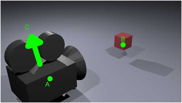
Figure 4.1: LookAtMatrix
Figure 4.1 depicts a camera looking at a cube. Two points are highlighted in bright green, and there is also a prominent green arrow. Point A corresponds to the position of the camera; it defines the location in world coordinates that the camera is positioned. This is the first vector of the three vectors in the call to XMMatrixLookAtRH from the previous code table.
Point B defines the point that the camera is looking towards; it determines the direction the camera is facing. This corresponds to the second vector in the call to XMMatrixLookAtRH in the previous code table. There happens to be a box in the diagram at this point, but a camera can look toward a point whether there is an object there or not.
Point C corresponds to the up vector; it is the direction that the top of the camera is pointing toward. Notice that without specifying an up vector, the camera is free to roll left or right and still look at the little box from the same position. The up vector is the third and final vector in the call to XMMatrixLookAtRH from the previous code table. By specifying all three of these vectors, we have defined exactly where a camera is positioned, what it is looking towards, and its orientation. Notice that the up vector is a direction, not a point, and it is relative to the camera.
Vertex and Pixel Shaders
And now we come to the most powerful and flexible part of the DirectX API: shaders. We have a buffer on the GPU and we wish to tell the GPU to render its contents. We do this by writing small programs. The first is a vertex shader. A vertex shader’s code executes once for every vertex in a vertex buffer. A pixel shader’s code executes once for every pixel in a scene.
Vertex Shader
Before we dive into vertex shaders, we should take some time to look at what vertex shaders are used for. In the chapter titled Introduction to 3-D Graphics, under the section “Model, World, and View Space,” we looked at transforming the coordinates of a model from its original local coordinates to world coordinates. We can place the model anywhere we like in a scene. We can reuse the same model and place multiple copies at different locations. We could also change the size of the objects, turn them upside-down, etc.
The next step, once all of our models are all placed into the world somewhere, is to place a viewer: a camera or eye, something to look at the scene. When we place a viewer into a DirectX scene, what we actually do is rotate and move the whole world such that we can determine the objects that are visible to the camera and render them.
The vertex shader is responsible for the above mentioned transformations. It converts models from local coordinates to view space. After the models are placed and camera is oriented, a vertex shader usually transforms all the points again so that the projection of the scene is correct. It does this using the projection matrix. When the vertex shader is finished placing all the models, the viewer and the projection is applied, and the resulting vertices are sent to the next shader. In our case, the next stage is the pixel shader, although a rasterizer pipeline stage will be called implicitly behind the scenes to turn the vectors from the vertex shader into pixels for the pixel shader.
The best way to see how a vertex shader works is to create one. To add a new vertex shader to your project, right-click on the project’s name in the solution explorer and select Add new item from the context menu (see Figure 4.2).
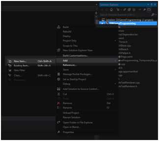
Figure 4.2: Adding a New Item
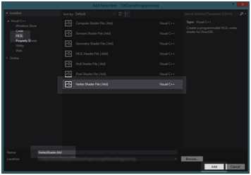
Figure 4.3: Adding a Vertex Shader
Select HLSL from the side panel and Vertex Shader File (.hlsl) from the middle panel (see Figure 4.3). I have left the filename as VertexShader.hlsl. Once you are done, click Add. Visual Studio will write a small example vertex shader for us and add it to our project. Replace the code with the code from the following code table.
// VertexShader.hlsl // The GPU version of the constant buffer cbuffer ModelViewProjectionConstantBuffer : register(b0) { matrix model; matrix view; matrix projection; }; // The input vertices struct VertexShaderInput { float3 position : POSITION; float3 color : COLOR0; }; // The output vertices as the pixel shader will get them struct VertexShaderOutput { float4 position : SV_POSITION; float3 color : COLOR0; }; // This is the main entry point to the shader: VertexShaderOutput main(VertexShaderInput input) { VertexShaderOutput output; float4 pos = float4(input.position, 1.0f); // Use constant buffer matrices to position the vertices: pos = mul(pos, model); // Position the model in the world pos = mul(pos, view); // Position the world with respect to a camera pos = mul(pos, projection);// Project the vertices output.position = pos; // Pass the color of the vertices to the pixel shader output.color = input.color; return output; } |
This file is written in the HLSL language. This language is very similar to C++. We will examine the language in a little more detail later. Briefly, you will see a constant buffer (cbuffer) defined at the top of the file. This is the shader’s version of the constant buffer we created earlier. The m_constantBufferGPU points to this buffer.
There are two structures defined: VertexShaderInput and VertexShaderOutput. The input to a vertex shader is a vertex buffer. We have already created and copied our triangle to the GPU as a vertex buffer. It is extremely important to note that this structure (VertexShaderInput) is exactly the same as the Vertex structure we defined in the Model class. Coordination of the same data types between the CPU and the GPU can be very confusing. XMFLOAT3 for the CPU is exactly the same thing as FLOAT3 for the GPU.
The second structure is the output of the vertex shader; this will pass to the pixel shader that we are about to write. The real magic in this shader lies in the three calls to the mul intrinsic. This is the intrinsic for a standard matrix multiplication. This method multiplies the positions of the vertices, first by the model matrix, then by the view matrix. Finally, they are multiplied by the projection matrix, which will result in the final position of the 3-D vertices that are visible in the viewing frustum. After the vertices are positioned, the color of each is copied to the output. Whatever the vertex shader returns will be given to the pixel shader. Note that the pixel shader has a float 4 instead of a float 3 for its position element.
Pixel Shader
A pixel shader executes its code once for every pixel that the rasterizer stage of the pipeline passes to it. These pixels depend completely on the vertex shader, since it is the vertex shader that determines where the models are and the position of the camera. The vertex shader also uses the projection matrix to specify how wide the viewing angle is, how near and how far the camera can see, etc. The visible pixels will be determined by the rasterizer stage and passed to the pixel shader. The rasterizer stage of the pipeline is passed the output from the vertex shader. It determines which pixels are going to be visible on the user’s screen, and it calls the pixel shader for every visible pixel. The rasterizer passes the output from the vertex shader to the pixel shaders. The pixel shaders can color pixels with different hues; they can apply textures and lighting effects to the pixels as well.
To add a pixel shader, follow the same steps as Figure 4.2 and Figure 4.3, only select a Pixel Shader file (.hlsl) from the window instead of a vertex shader. Once again, I have left the file’s name as the default, so mine will be called PixelShader.hlsl. Once again, Visual Studio will create the new shader and write some example HLSL code. Replace the code with the following code table.
// PixelShader.hlsl // Input is exactly the same as // vertex shader output! struct PixelShaderInput { float4 position : SV_POSITION; float3 color : COLOR0; }; // Main entry point to the shader float4 main(PixelShaderInput input) : SV_TARGET { // Return the color unchanged return float4(input.color,1.0f); } |
The pixel shader is very simple; it begins with a structure definition of the type of input. This must match the VertexShaderOutput exactly, because they are one and the same thing. The output from the vertex shader is the input to the pixel shader.
The main body of the pixel shader does almost nothing other than pass on the colors of the pixels. It also adds a fourth component to the RGB, which is the Alpha channel (1.0f).
You should be able run your application at this point. It will not look any different, but if you navigate to the output directory, you will see two new files have been compiled: VertexShader.cso and PixelShader.cso (see Figure 4.4).
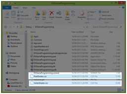
Figure 4.4: CSO Files
These files are an intermediate version of our shaders. Visual Studio has compiled our HLSL source code files to a binary format using the FXC.exe compiler. CSO stands for Compiled Shader Object file. From here we need our graphics card’s driver to compile the CSO files to a binary format that the particular hardware inside the computer understands. This is good because all GPUs understand different machine code, but we can create shaders with the HLSL language and the graphics card drivers compile them to specific machine code. In this way, they will run on AMD graphics cards as well as NVidia or integrated graphics cards.
Adding Shader Classes
The next step towards rendering our triangle is compiling the shaders from the CSO files. We need a method that reads the files; this could be placed anywhere, but I have selected to place it in the DirectXHelper.h file. The following code table highlights the changes to the DirectXHelper.h file.
// DirectXHelper.h #pragma once using namespace Microsoft::WRL; using namespace Windows::ApplicationModel; using namespace Windows::Graphics::Display; namespace DX { inline void ThrowIfFailed(HRESULT hr) { if (FAILED(hr)) { // Set a breakpoint on this line to catch Win32 API errors. throw Platform::Exception::CreateException(hr); } } // Reads bytes from the specified file in the current folder inline Platform::Array<byte>^ ReadData(_In_ Platform::String^ filename) { CREATEFILE2_EXTENDED_PARAMETERS extendedParams = {0}; extendedParams.dwSize = sizeof(CREATEFILE2_EXTENDED_PARAMETERS); extendedParams.dwFileAttributes = FILE_ATTRIBUTE_NORMAL; extendedParams.dwFileFlags = FILE_FLAG_SEQUENTIAL_SCAN; extendedParams.dwSecurityQosFlags = SECURITY_ANONYMOUS; extendedParams.lpSecurityAttributes = nullptr; extendedParams.hTemplateFile = nullptr; Platform::String ^path = Platform::String::Concat(Package::Current->InstalledLocation->Path, "\\");
Wrappers::FileHandle file(CreateFile2(Platform::String::Concat(path, filename)->Data(), GENERIC_READ, FILE_SHARE_READ, OPEN_EXISTING, &extendedParams)); if (file.Get() == INVALID_HANDLE_VALUE) throw ref new Platform::FailureException(); FILE_STANDARD_INFO fileInfo = {0}; if (!GetFileInformationByHandleEx(file.Get(), FileStandardInfo, &fileInfo, sizeof(fileInfo))) throw ref new Platform::FailureException(); if (fileInfo.EndOfFile.HighPart != 0) throw ref new Platform::OutOfMemoryException(); Platform::Array<byte>^ fileData = ref new Platform::Array<byte>(fileInfo.EndOfFile.LowPart); if (!ReadFile(file.Get(), fileData->Data, fileData->Length, nullptr, nullptr)) throw ref new Platform::FailureException(); return fileData; } } |
The method previously used reads binary data from the file specified as a parameter and returns it. The file must reside in the application’s directory, and the method does not accept full file paths. This code will cause a subtle problem. Currently, in the pch.h file we are likely referencing the wrl/client.h header. We need to reference the wrl.h header instead, because this header defines some of the structures used in the ReadData method like file and the Wrappers namespace. Change the header in the pch.h file as per the following code table.
// pch.h #pragma once // #include <wrl/client.h> #include <wrl.h> #include <d3d11_1.h> #include <d2d1_1.h> #include <d2d1effects.h> #include <dwrite_1.h> #include <wincodec.h> #include <agile.h> #include <DirectXMath.h> #include "App.xaml.h" |
Next we can add two classes: one to wrap up the vertex shaders and another to wrap up the pixel shaders. First we will add the class called VertexShader. Add two new files to your project, VertexShader.h and VertexShader.cpp. The code for these files is specified in the two following code tables.
// VertexShader.h #pragma once #include "DirectXHelper.h" class VertexShader { private: ID3D11VertexShader*m_vertexShader; Microsoft::WRL::ComPtr<ID3D11InputLayout> m_inputLayout; public: // Loads a compiled vertex shader from a CSO file void LoadFromFile(ID3D11Device *device, _In_ Platform::String^ filename); // Returns pointer to vertex shader ID3D11VertexShader* GetVertexShader() { return m_vertexShader; } // Returns pointer to input layout ID3D11InputLayout* GetInputLayout() { return m_inputLayout.Get(); } }; |
// VertexShader.cpp #include "pch.h" #include "VertexShader.h" void VertexShader::LoadFromFile(ID3D11Device *device, _In_ Platform::String^ filename) { // Read the file Platform::Array<unsigned char, 1U>^ fileDataVS = DX::ReadData(filename); // Crreate the vertex shader from the file's data DX::ThrowIfFailed(device->CreateVertexShader(fileDataVS->Data, fileDataVS->Length, nullptr, &m_vertexShader)); // Describe the layout of the data const D3D11_INPUT_ELEMENT_DESC vertexDesc[] = { { "POSITION", 0, DXGI_FORMAT_R32G32B32_FLOAT, 0, 0, D3D11_INPUT_PER_VERTEX_DATA, 0 }, { "COLOR", 0, DXGI_FORMAT_R32G32B32_FLOAT, 0, 12, D3D11_INPUT_PER_VERTEX_DATA, 0 }, }; DX::ThrowIfFailed(device->CreateInputLayout (vertexDesc,ARRAYSIZE(vertexDesc), fileDataVS->Data, fileDataVS->Length, &m_inputLayout)); } |
The code above reads a CSO file and creates a vertex shader from it called m_vertexShader. The D3D_INPUT_ELEMENT_DESCRIPTION is used to specify the exact layout of the vertices this shader will accept. Each element is described using the following.
- LPCSTR SemanticName;
- UINT SemanticIndex;
- DXGI_FORMAT Format;
- UINT InputSlot;
- UINT AlignedByteOffset;
- D3D11_INPUT_CLASSIFICATION InputSlotClass;
- UINT InstanceDataStepRate;
SemanticName: This is a string representing the intended use of the element. This should match the VertexShaderInput structure from the VertexShader.hlsl file.
SemanticIndex: This is used when there is more than one element with the same semantic name; we have only a POSITION and COLOR, so we do not use this index.
Format: This must be the exact format of the data for each element. We used XMFLOAT3 to create our vertex buffer, so the format for both the color and the position elements is DXGI_FORMAT_R32G32B32_FLOAT. For a complete list of all the possible formats, right-click on this constant and select Go to Definition from the context menu. Once again, this needs to match the Vertex structure on the CPU, which we defined in the Model.h file as well as the VertexShaderInput structure in the VertexShader.hlsl file.
Aligned Byte Offset: This is the offset within the structure that the element falls. The POSITION element is first in our structure, so its offset is 0. The COLOR element is after the position element, which is 3 floats or 12 bytes wide. The offset of the COLOR element within the structure is 12. For convenience, you can use D3D11_APPEND_ALIGNED_ELEMENT for this value and the data will be packed automatically. Be aware that D3D11_APPEND_ALIGNED_ELEMENT could not possibly know the correct way to pack all data, and it relies on the CPU to use standard aligned packing.
Input Slot Class: This is the class of the data. Each vertex has a position and color so we use D3D11_INPUT_PER_VERTEX_DATA here.
The InputSlot and InstanceDataStep are used when there is more than one assembler or for doing instancing; these can be ignored for the time being.
Next, we will add a class to wrap up our pixel shader. Add two files, PixelShader.h and PixelShader.cpp. The code for these files is specified in the following two code tables.
// PixelShader.h #pragma once #include "DirectXHelper.h" class PixelShader { private: ID3D11PixelShader* m_pixelShader; public: // Loads a compiled pixel shader from a CSO file void LoadFromFile(ID3D11Device *device, _In_ Platform::String^ filename); // Returns pointer to pixel shader ID3D11PixelShader* GetPixelShader() { return m_pixelShader; } }; |
// PixelShader.cpp #include "pch.h" #include "PixelShader.h" void PixelShader::LoadFromFile(ID3D11Device *device, _In_ Platform::String^ filename) { // Read the file Platform::Array<unsigned char, 1U>^ fileDataPS = DX::ReadData(filename); // Create a pixel shader from the data in the file: DX::ThrowIfFailed(device->CreatePixelShader(fileDataPS->Data, fileDataPS->Length, nullptr, &m_pixelShader)); } |
The PixelShader class is a little simpler than the VertexShader class, since we do not need to describe the layout of the data. It just reads the file and creates a shader from it.
Next, we need to add references to the shader headers (PixelShader.h and VertexShader.h) to the SimpleTextRenderer.h file. These changes are highlighted in the following code table.
// SimpleTextRenderer.h #pragma once #include "DirectXBase.h" #include "Model.h" #include "VertexShader.h" #include "PixelShader.h" |
Add two new member variables to this class to hold our shaders. I have called them m_vertexShader and m_pixelShader, and I have added them to the end of the class declaration.
private: Model *m_model; Microsoft::WRL::ComPtr<ID3D11Buffer> m_constantBufferGPU; ModelViewProjectionConstantBuffer m_constantBufferCPU; // Shaders VertexShader m_vertexShader; PixelShader m_pixelShader; }; |
Now that we have declared our shaders, we need to have them load the appropriate files. The shaders are a device dependent resource, so this should be done in the CreateDeviceResources method of the SimpleTextRenderer class, in the SimpleTextRenderer.cpp file. I have placed this after the creation of the constant buffer and highlighted the changes in the following code table.
// Create the constant buffer on the device CD3D11_BUFFER_DESC constantBufferDesc(sizeof (ModelViewProjectionConstantBuffer), D3D11_BIND_CONSTANT_BUFFER); DX::ThrowIfFailed(m_d3dDevice->CreateBuffer(&constantBufferDesc, nullptr, &m_constantBufferGPU)); // Load the shaders from files (note the CSO extension, not hlsl!): m_vertexShader.LoadFromFile(m_d3dDevice.Get(), "VertexShader.cso"); m_pixelShader.LoadFromFile(m_d3dDevice.Get(), "PixelShader.cso"); } |
We should position our triangle in world space by setting the m_constantBufferCPU.model matrix. I will place the triangle at the origin (0.0f, 0.0f, 0.0f). The position of the triangle can be set in the SimpleTextRenderer::Update method. The following code table highlights the code to position the model.
XMVectorSet(0.0f, 0.0f, 0.0f, 0.0f),// Look at XMVectorSet(0.0f, 1.0f, 0.0f, 0.0f) // Up vector ))); // Position the triangle model XMStoreFloat4x4(&m_constantBufferCPU.model, XMMatrixTranspose( XMMatrixTranslation(0.0f, 0.0f, 0.0f))); } |
Rendering the Model
Finally, we can now render the triangle with the shaders. There are a few steps to rendering, but most of them are called once per call to Render. The steps to rendering are as follows:
- Clear the Depth Stencil Buffer: We have begun a new round of rendering and the depth data in the depth stencil must be reset. For the current round of rendering, the GPU hasn’t examined any pixels yet, and there are presently no pixels in front of or behind any others.
- Set the Render Target: The GPU needs to know the render target; this is where it is rendering to. In our present example, we are rendering to a target that will shortly be flipped to the screen and shown to the user.
- Reset the index of the current vertex being rendered: The GPU will maintain the index of the last vertex it rendered from the previous round of rendering. We want it to start rendering our model again from vertex number 0.
- Set resources to point to our triangle and shaders: We need to set all the resources (the input layout, the subresoucres, the current vertex and pixel shaders, the constant buffer) to point to our triangle, accompanying buffers, and shaders.
The final Render method, after adding all of these changes to the SimpleTextRenderer class, is presented as the following code table.
void SimpleTextRenderer::Render() { m_d3dContext->ClearRenderTargetView(m_d3dRenderTargetView.Get(), (float*) &XMFLOAT3(0.39f, 0.58f, 0.93f)); // Clear to cornflower blue
// Clear the depth stencil m_d3dContext->ClearDepthStencilView(m_d3dDepthStencilView.Get(), D3D11_CLEAR_DEPTH, 1.0f, 0); // Set the render target m_d3dContext->OMSetRenderTargets(1, m_d3dRenderTargetView.GetAddressOf(), m_d3dDepthStencilView.Get()); // Set to render triangles UINT stride = sizeof(Vertex); // Reset to the frist vertices in the buffer UINT offset = 0; m_d3dContext->IASetPrimitiveTopology(D3D11_PRIMITIVE_TOPOLOGY_TRIANGLELIST);
// Set the input layout m_d3dContext->IASetInputLayout(m_vertexShader.GetInputLayout()); // Set the vertex shader m_d3dContext->VSSetShader(m_vertexShader.GetVertexShader(), nullptr, 0); // Set the vertex shader's constant buffer m_d3dContext->VSSetConstantBuffers(0, 1, m_constantBufferGPU.GetAddressOf()); // Set the pixel shader m_d3dContext->PSSetShader(m_pixelShader.GetPixelShader(), nullptr, 0); // Load the data from the CPU into the GPU's constant buffer m_d3dContext->UpdateSubresource(m_constantBufferGPU.Get(), 0, NULL, &m_constantBufferCPU, 0, 0);
// Set the vertex buffer m_d3dContext->IASetVertexBuffers(0, 1, m_model->GetAddressOfVertexBuffer(), &stride, &offset);
// Render the vertices m_d3dContext->Draw(m_model->GetVertexCount(), 0); m_d2dContext->BeginDraw(); HRESULT hr = m_d2dContext->EndDraw(); if (hr != D2DERR_RECREATE_TARGET) { DX::ThrowIfFailed(hr); } } |
At this point, you should be able to compile and run the application and see a rather fetching colored triangle in the top half of the screen.
- 1800+ high-performance UI components.
- Includes popular controls such as Grid, Chart, Scheduler, and more.
- 24x5 unlimited support by developers.