
Database Design Succinctly®

CHAPTER 2
Data Models
To understand how to make a user’s view of their information and create a database system, we rely on three primary models: conceptual, logical, and physical. Each model has a different audience and role. In this chapter, we will briefly describe the models, who uses each one, and the role that typically creates each model.
Conceptual data model
A conceptual data model is a very high-level view of the entities and actions that the database system will model. It is intended to be very nontechnical and not very detailed. It should provide just enough information for a person to get an overview of the type of data and processes the system will contain.
A conceptual model should be created very early in the data modeling process. It generally relies on the defined use cases to extract the entities that the system will model. A business analyst or manager typically is the primary resource for defining the conceptual model. Figure 8 shows a simple conceptual model for an ordering system.

Figure 8: Conceptual model (order system)
Very little detail is provided by this model; it’s just an overview of the primary entities (customers, orders, and invoices) and relationships (customer has multiple orders, the order has one invoice) among those entities.
Logical data model
The logical model consists of entities, attributes, and relationships between entities. It does not address the physical implementation, but rather should be database-agnostic. A good logical model could be implemented in any database management system. You should also be able to design the model using an object database or even a collection of flat files.
Entities
An entity is a person, place, or thing of which the model needs to keep track. Each entity will typically be represented by one or more tables in the physical model. For the logical model, we want each entity to have a name and the attributes of that entity. In addition to attributes, one or more attributes will serve as a key (the unique identifier for the entity).
Attributes
Attributes are properties associated with an entity. For example, a customer entity most likely has a name, address, and phone number. In the logical model, we are defining attributes at a higher level than we need for implementation. The following table shows some examples of logical versus physical attributes.
Table 1: Logical versus physical attributes
Logical attribute | Physical model |
|---|---|
Address | Name, Address Line(s), City, State, Country, Postal Code |
Name | First, Last, Middle Initial, Salutation |
Business unit | Organization, Division, Department, Website URL |
Ideally, the logical attributes will have an associated standard definition of the components of the attribute (so all address attributes, regardless of entity, should look the same).
Relationships
Relationships in the logical model describe how entities interact with each other. There are three relationship types to consider.
One-to-one (1:1)
There is a direct relationship between the two entities and a single connection. For example, an order is associated with a single customer. An invoice is associated with a single order, and so on. Note that a 1:1 relationship only refers to a single occurrence. A customer may have multiple orders, but each order is associated with only one customer.
One-to-many (1:n)
A one-to-many relationship occurs when an entity can have multiple occurrences of another entity. In our example, a customer has a one-to-many relationship with orders (so a customer can have many orders), but each order only has one customer. Similarly, the order has multiple line items, but each line item is linked to a single order.
Many-to-many (n:n)
Our product entity might be supplied by multiple vendors, and each vendor might supply multiple products. This is a many-to-many relationship between the two entities. Most relational databases don’t directly support this type, but it is a fairly common practice to define this type using a third table, sometimes called a junction table, to link them together.
Figure 9 shows our logical model for the ordering system based on the conceptual model we defined earlier.

Figure 9: Logical data model
Physical data model
Once the logical model is completed, a database developer or administrator will implement the logical model as tables and columns in a database management system. Most entities will be represented by a table (or multiple tables if needed), and the relationships will be defined via indexes and foreign keys.
At this point, we are concerned with the target database, and the developer will likely create the model using the columns and constraints that the target database uses. While the SQL language is common among SQL dialects, there are variations among the various products.
Figure 10 shows our physical model for the ordering system, derived from the logical model we designed earlier. The model assumes Microsoft SQL Server is the target database.
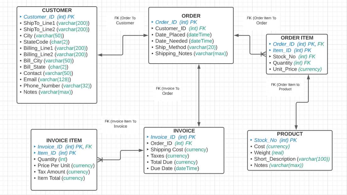
Figure 10: Physical data model
The physical model might contain additional information, such as database constraints, nullable columns, and views versus tables. We will cover this in more detail in a later chapter.
Summary
The three models described here take the customer’s understanding of their information and translate that understanding into a model that can be implemented in a database.
Note: We are focusing on relational databases, such as Microsoft SQL Server and Oracle. Nonrelational databases, such as MongoDB and Redis, offer a different approach than tables to hold the data.
- 1800+ high-performance UI components.
- Includes popular controls such as Grid, Chart, Scheduler, and more.
- 24x5 unlimited support by developers.