
CUDA Succinctly®

CHAPTER 3
Architecture
We are about to run quickly through many terms which must be understood in order for CUDA to be appreciated. It is natural to be confused by this onslaught of terms. If this chapter is confusing, read it and the next chapter a few times, code the examples in Chapter 4, and examine the effect of changing the code. All of these concepts are connected and one cannot be described without knowing the others.
The GPU is called the device; the CPU and the rest of the system are called the host. The host is in control of the system memory and other peripheral hardware, including the device itself. The device has its own architecture and memory, often (but not always) separate from the system memory. The device is not able to control things such as hard drives, system RAM, or any other peripherals; this is all the domain of the host.
In computer systems where the device is on-board (i.e. included as part of the original build hardware and not added as an expansion card of some kind), it may share some of the main system memory. In these circumstances, the operating system and graphics driver may partition some of the system memory for specific use by the device as graphics RAM. This memory effectively becomes dedicated graphics RAM; it is programmed in exactly the same way as physical graphics RAM. For the remainder of this book, however, I will assume that this is not the case and that the device has its own dedicated memory.
The device communicates with the host through the PCI bus as shown in Figure 3.1.
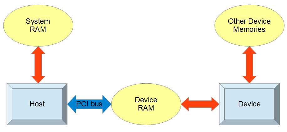
Figure 3.1: Device and Host
All communication between the host and the device passes through the PCI bus. The host is able to read and write its own system RAM as well as the device RAM through special CUDA API function calls. The device can also read and write device RAM but it has an additional hierarchy of other memory spaces, which we will examine in detail.
The device RAM pictured in Figure 3.1 is often a special, fast type of DDR RAM (double data rate) called graphics DDR (GDDR). This main memory area of the device is often quite large (one or more gigabytes is not uncommon today). The amount of this device RAM is often cited as “dedicated graphics RAM” in the specifications of a GPU. As mentioned, in systems without dedicated graphics RAM, the device RAM will actually be a portion of system RAM and only separated conceptually. Usually, the device’s RAM chips sit on the device itself and the only communication channel to the host is the PCI bus socket on the motherboard the device is plugged into.
Kernels, Launch Configurations, and dim3
Kernels
CUDA kernels are functions that are designed to be executed by the device. They usually differ from regular host functions in that they are meant to be executed by many threads simultaneously. The host tells the device to run kernels by using something called a kernel launch. A kernel launch is similar to a regular C function call, only it has a launch configuration beside the function’s name. Listing 3.1 shows a kernel launch.
SomeKernel<<<12, 64>>>(a, b, c); |
Listing 3.1: Kernel Launch
The launch configuration (Listing 3.1) is described with triple right-angle brackets (<<< and >>>); it configures the device’s execution units so the kernel’s code can be executed by many threads. Here, the kernel would be launched with 12 blocks—each containing 64 threads; a, b and c are the parameters. We will look at launch configurations in more detail momentarily.
Restrictions on Kernels
Kernels have a syntax almost identical to regular C++ or C but there are some restrictions. Kernels cannot be recursive, they cannot have a variable number of arguments, and they must return void. They are marked with the __global__ specifier and they are called by the host.
Not all device functions have to return void, only __global__ kernels have this restriction. Helper functions, callable from the device and marked with __device__, need not return void. As of Fermi (Fermi is the name of the architecture of NVIDIA devices from the GeForce 400 series), __device__ functions are allowed a limited depth of recursion as illustrated in Listing 4.6.
Launching a Kernel
The launch configuration is specified after the kernel’s name in a kernel call. The launch configuration can contain two or three parameters. The first two parameters specify the number of blocks in the grid and the number of threads in each block (we will describe threads and blocks shortly). The third parameter specifies the amount of dynamic shared memory.
Kernel_Name<<<gridSize, blockSize>>>(params…);
Kernel_Name<<<gridSize, blockSize, dynamic_Shared_Memory>>>(params…);
Kernel_Name is the name of the kernel function being launched. The gridSize parameter is the number of blocks in the grid. And the blockSize parameter is the number of threads in each block. The gridSize and blockSize parameters can be either dim3 (described next) or regular integers.
dim3
The dim3 data type is a structure composed of three unsigned integers: x, y, and z. It is used to specify the sizes of grids and blocks of multiple dimensions. It is also the data type of the idx indices (i.e., threadIdx, blockIdx, blockDim, and gridDim) which are used by threads to calculate unique IDs in kernels. In Listing 3.1, the launch configuration was specified using integers; in Listing 3.2, the launch configuration is specified using dim3.
dim3 gridSize(10, 10, 10); dim3 blockSize(32, 32); Call_Kernel<<<gridSize, blockSize>>>(params...); |
Listing 3.2: Multidimensional Kernel Launch
Listing 3.2 illustrates the code for a multidimensional kernel launch using dim3 structures for the block and grid size. The launch configuration uses two dim3 structures to specify the arrangement of threads in the grid. The gridSize parameter specifies that the grid is to be a three-dimensional array of blocks, with dimensions 10, 10, and 10 (this means a total of 1,000 blocks will be launched). The blockSize parameter specifies that each block is to be composed of a two-dimensional grid of threads with dimensions 32 and 32. This launch configuration will result in a total of 1,000 blocks with 32 × 32 threads in each block, for a total thread count of 1,024,000 threads.
The number of blocks and threads launched by the host can exceed the physical capabilities of the device. If your device is able to execute 768 threads per core and you have 16 cores, then the device can potentially execute 16 × 768 threads in parallel. But this number (16 × 768 = 12,288) is only the number of blocks and threads the device can physically execute in parallel; it is not a limit on the sizes specified by the launch configuration. The device has a scheduler which allocates blocks to physical cores for execution. When a core finishes executing a block, the scheduler will either give the core another block to execute or, if there are no more blocks to be executed in the launch, the kernel will complete.
The dim3 data type supplies constructors for defining single-dimension, 2-D, and 3-D instances of the structure. The single-dimensional version (using a constructor with one parameter) initializes a dim3 structure with only the X component set; the other dimensions default to 1. The 2-D constructor (which takes two operands) can be used to set the X and Y dimensions of a dim3 structure and the Z dimension is set to 1. The 3-D constructor allows the programmer to set all three dimensions.
Multidimensional grids and blocks are a theoretical construction provided to simplify programming when data is inherently multidimensional. For instance, when working with a 2-D image, it might be convenient to launch 2-D blocks of threads and have each thread work with a single pixel.
Threads, Blocks, the Grid, and Warps
The device is a physical piece of hardware, a dedicated graphics card which plugs into the motherboard of the computer. The device consists of some number of execution units called streaming multiprocessors (SM). An SM has a collection of thread processors, a register file, double precision unit, and shared memory. The SMs are capable of executing many threads simultaneously, with the thread processor units each executing a different thread.
Threads
In parallel programming (and CUDA), a thread is a conceptual execution unit. It is a theoretical object which executes a single line of serial instructions. Parallel programming is entirely based on running concurrent threads. Instead of using a single thread to solve a problem, we can split problems into separate subproblems and use multiple threads at once to solve the larger problem. A single thread can be illustrated as an arrow with a squiggly tail as per Figure 3.2. Each thread in CUDA has an index called threadIdx which, along with the blockIdx and blockDim, can be read in the kernels and which is of type dim3.
![]()
Figure 3.2: A Thread
Note: Concurrency has a specific meaning in parallel programming. Concurrent threads may or may not actually execute in parallel (at exactly the same time). The order that threads execute is theoretically outside the programmer's control. Two threads are said to be concurrent if they could potentially access the same variable at the same time, or if it impossible to tell based on the code which of the threads will access first.
Thread Blocks
In CUDA, we group threads together into thread blocks. A thread block is a collection of threads which can easily communicate with each other. Each block has a block number (blockIdx) which is unique within the grid and which is a dim3 type. Threads can use the blockIdx in kernels as a reference to which block the thread belongs. Threads can also reference the blockDim structure (also a dim3) which is a record of how many threads there are per block.
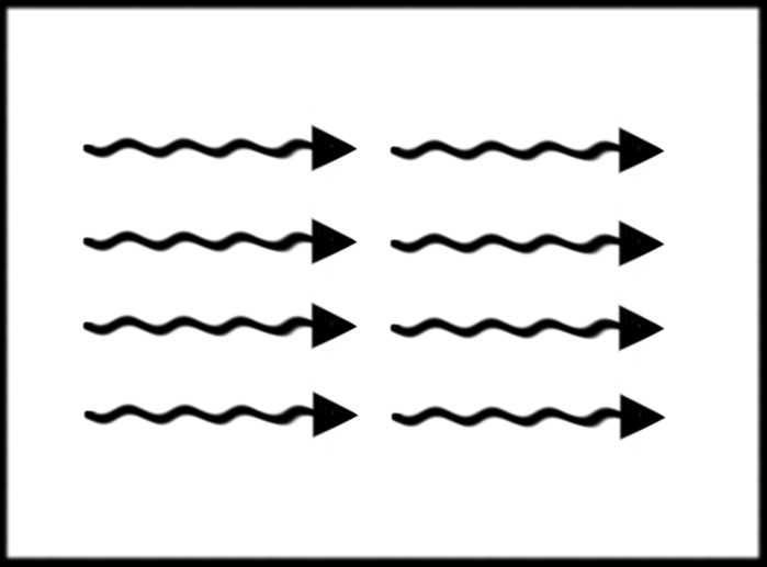
Figure 3.3: A Thread Block
Grid
When we launch a kernel, we specify a collection of thread blocks called a grid. A thread block is a collection of threads and the grid is a collection of thread blocks. Figure 3.4 depicts a 2-D grid of thread blocks.
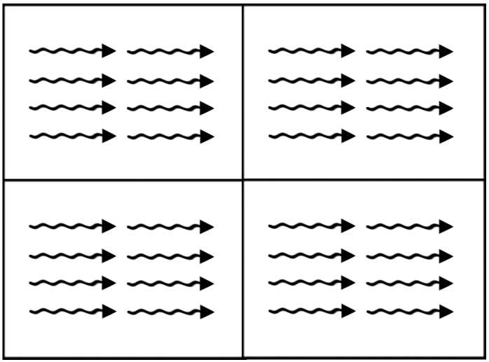
Figure 3.4: A grid of thread blocks
There is a maximum number of threads per block allowed (1,024 on Fermi, and in the previous example) but the maximum number of blocks per grid is very large. The total number of threads that runs concurrently is the size of the grid multiplied by the size of each block in threads. Threads can use the gridDim structure, which is a dim3, as a record of how many blocks the grid contained when the kernel was launched.
The extra layer of abstraction from threads to thread blocks means that, as new hardware becomes available, it can execute more blocks simultaneously and the code need not be changed. Threads within blocks have fast communication channels with each other but they cannot easily communicate with threads of other blocks.
Warps
When the device executes a kernel, it splits threads into groups of 32, called warps. Each warp contains 32 threads with consecutive threadIdx values. All threads of a warp are from the same block.
The threads of a warp execute instructions in lockstep; this means they all execute the same instruction at the same time unless there is a branch. If the threads are in a warp branch (branching occurs when there is a condition such as an if statement and some threads take one path while others take another path), the device executes the two paths for the branch in serial. Managing the branching of threads within warps is an important consideration for performance programming.
Warps are also an important consideration for resource management. As mentioned, warps always consist of 32 threads, with consecutive threadIdx values from the same thread block. Every warp allocates enough resources for all 32 threads whether or not there are 32 threads in the block. This means, if the number of threads per block is less than 32, then the device will allocate resources for a complete warp of 32 threads and some of the resources will be wasted.
Even if a thread block contains more than 32 threads, or if it consists of any number of threads not evenly divisible by 32, then the block will waste resources in one of the warps. It is recommended that thread blocks have a number of threads which is evenly divisible by 32.
Device Memories
There are many different types of memory in the GPU, each having a specific use along with various limitations and performance characteristics. Figure 3.5 illustrates the theoretical relationship between these memories. The two boxes marked “Block 0” and “Block 1” represent thread blocks; there are usually many more than two of these running concurrently. Each block has some amount of shared memory and a collection of threads. The threads each have access to their own local memory and registers.
In addition to the memory spaces which blocks and threads access individually (i.e., the shared memory, local memory, and registers), there are several memory spaces that all threads can access. All threads and the CPU host have access to the global memory, the constant memory, and the texture memory.
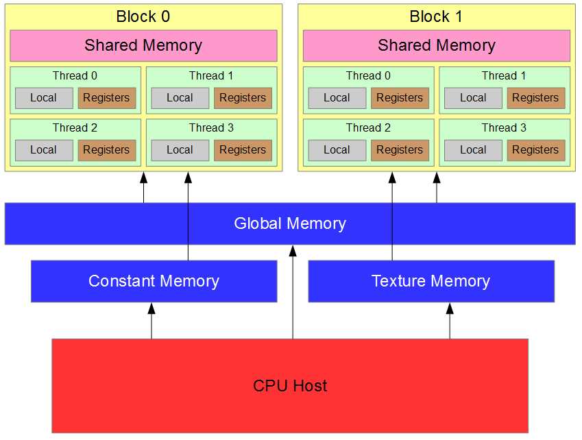
Figure 3.5: Memory Hierarchy
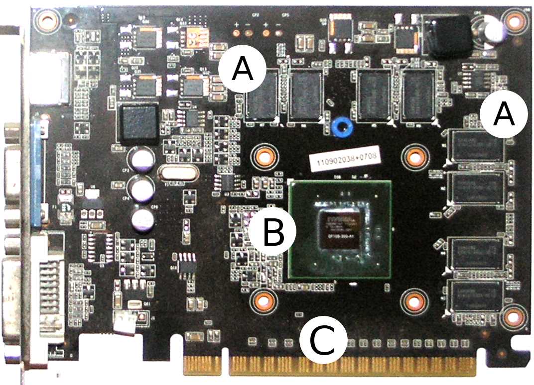
Figure 3.6 shows a typical graphics card. A graphics card is a combination of hardware including the GPU itself. It is common to refer to an entire graphics card as a GPU, but the GPU is actually only the main chip on a graphics card, like the chip marked B in Figure 3.6. This particular graphics card was designed by Gainward and features an NVIDIA GT 440. The heat sink (which is a large fan for cooling the device) has been removed to better view the layout.
Examining the image in Figure 3.6, you will notice four horizontal and four vertical black rectangles marked with an A. These rectangles are the device’s main graphics memory chips. The device’s main memory is used for global, local, constant, and texture memory (all of which will be explained shortly). Each of these memories also has associated caches, and the caches are inside the GT 440 chip.
The NVIDIA GT 440 chip itself is marked B. It is a small black square sitting on a larger green square. The SMs, including shared memory, caches, CUDA cores, and registers, are all located inside the chip.
The golden pins marked with a C plug into the system’s motherboard. It is through these pins that the host communicates with the device. There are two related terms, “on-device” and “on-chip”. On-device means anywhere on the entire card, while on-chip means inside the GT 440 chip itself.
Registers
The fastest memory in the device is the registers. Registers are fundamental to the device and have no address because they are not in any type of RAM. The registers are hardware variables exposed to the programmer in software. They are essentially the workhorses of the device. They are on-chip (which, again, means they are physically located inside the SM). The SMs have a register file consisting of some limited number of registers which they can divvy out to the concurrent blocks.
Note: All computations are performed in the registers. This fact is often hidden from the programmer. There are no instructions which perform arithmetic, logic, or shifting on any of the other memories. When the device executes an operation on data in another memory space, it first copies the data into a register, then performs the operation on that data before copying the results back to the original location.
Threads do not share registers; each thread is given its own collection of registers with which to work. When the device runs out of registers, it causes what is called register spilling. The device will use global memory for extra storage space. When global memory is used in this way, it is called local memory. In this sense, local memory is not a distinct type of memory; it is the device’s way of using global memory for extra storage when it runs out of registers. We will discuss local memory in more detail later; it is used under other circumstances besides coping with register spilling.
Tip: The value reported as “Total number of registers available per block” in Device Query is the size of the register file per SM. To find the total number of registers available on your device, multiply this by the number of SMs. For instance, with the GT 430 in this machine, the number of multiprocessors (SMs) is 2, and there are 32,768 registers per block, so the total number of registers available on this device is 65,536.
To use a register in a kernel, you can simply declare a variable. If there are enough registers free (i.e. there is no register spilling), this will result in the variable being stored in a register. If, however, there are not enough registers free, the variable will be created in local memory and will physically reside in global memory. The distinction between registers, local memory, and global memory can be confusing. Generally speaking, you want to use as few registers per thread as possible and avoid register spilling. Local memory is not a distinct type of memory; it is a usage of global memory.
Shared Memory
Shared memory is shared between the threads of a block. It is very fast, running at almost the same speed as the registers, and it is on-chip. Shared memory is the same physical memory as the L1 cache for global memory (see the Caches section that follows). Shared memory is a way for programmers to control the L1 cache in the device. We will examine it in detail in Chapters 6 and 7 since careful use of shared memory can improve the performance of code substantially. Understanding shared memory is a big part of efficiently using the device.
Caches
On modern devices (from the Fermi generation and newer), there are two caches, L1 and L2. These caches are controlled almost entirely by the device. The L1 cache is on-chip, so it is exceptionally fast (only the registers are faster). The L2 cache is slower than the L1 cache but is still much faster than global memory. All reads and writes within global memory, including data copied from the host, gets processed in the L2 cache. When a thread makes a global memory request, the device first checks to see if the request can be satisfied from the L1 cache and, if it cannot, then the L2 cache is checked second. Only when neither of the caches can satisfy the request is global memory read; this final read is the slowest type of read available.
Caches are an automatic memory optimization system which the device controls to help reduce traffic on the global memory bus. The use of the caches by the device is fairly simple: when data is read from global memory for the first time, it is stored in the L1 cache (usually). The device assumes that the same data is likely to be requested again, and storing a copy in the L1 will mean that if it is requested again, it can be read very quickly the second time. After a while, as more and more values are stored in the L1, it eventually becomes full. At this point, when more data is read from global memory, the L1 cache must evict the oldest (least likely to be read) values and replace them with the newer data. Data evicted from the L1 goes to the L2 cache.
The L2 cache is much farther away from the chip than the L1 cache (leading to slower access times) but it is still closer than using global memory. The L2 cache is much larger than the L1 cache (see Device Query for the actual sizes of these memories on your device) but, unfortunately, must also eventually evict stale data in the same manner as the L1 cache.
As mentioned in the Shared Memory section, the L1 cache and shared memory are actually the same physical memory. Shared memory is a way to control the L1 cache.
Local Memory
Local memory is local to each thread. Data in local memory is not shared by any other threads in the grid. Local memory is physically the same memory as global memory. There are two circumstances under which global memory might be called local memory. Always remember that local memory is not a distinct type of memory but, rather, it is a particular way of using global memory.
The first circumstance under which global memory might be referred to as local memory is when register spilling occurs. When we create local variables within a thread's code (with normal variable declarations int j, float q, etc.), the device will assign these variables to a register but only if there are enough registers available. If there are no registers available, then the device will store the variable in global memory; this use of global memory is called local memory. The term “local memory” refers to the fact that other threads are not meant to access these variables. The variables are supposed to be local to each thread, just like the registers. The partitioning of variables into registers and memory is automatic. Local memory is far slower than the registers and you will generally want to minimize local memory usage as much as possible. You can examine the amount of local memory a kernel uses by profiling your application (see Chapter 8).
The second circumstance under which global memory will be used (and will be called local memory) is when structures and arrays are used within a kernel. The device stores variables in registers when it can, but structures and arrays require pointers in order to access their elements. When the device accesses a particular element of a structure or an array, it uses a base and offset pointer behind the scenes. This means that in order to use a structure or an array in a kernel, the variables require addresses to which they can be pointed. Registers do not have addresses so they cannot be used to store and access the elements of a structure or an array. So, structures and arrays are stored in the device's global memory. Just like register spilling, this usage of global memory is automatic and it is called local memory.
Constant Memory
Constant memory is a special memory on the device specifically designed for storing grid-wide constants. Constant memory cannot be set by the device (hence its name) but the host can set values in constant memory prior to calling a kernel (in this sense, it is not constant at all). Constant memory is cached in its own cache, unrelated to the L1 and L2 caches present in global memory.
Constant memory is very fast when all of the threads of a block read the same value (shared memory speeds). To create a variable in constant memory, mark it as __constant__. Constant memory is actually stored in global memory but, as mentioned earlier, because of its dedicated cache, it can be accessed very fast.
Tip: Use C++ constants (i.e. the const keyword) if the value of a variable will never change, and use __constant__ (device‘s constant memory) if the host needs the ability to alter the variable during the program’s execution. C++ constants become immediate values in machine code and do not take any cycles to read from memory (other than the initial reading of the instruction). On the other hand, device constants require a read from the constant memory. Constant memory is fast when cached but not as fast as no read at all.
If all of the threads of a warp do not access exactly the same value from constant memory, the accesses will be serialized. If all threads of a warp do access exactly the same value, the access will be extremely fast, the memory will be read once from the constant cache, and will be broadcast to the threads. If the requested memory is not in the constant cache, then the first read will be slow as the data must come from global memory; subsequent reads will result in a fast cache hit.
The host can change the value of constant memory using the cudaMemcpyToSymbol API function call. The syntax is as follows:
cudaError_t cudaMemcpyToSymbol(__constant__ devConst, const void* src_ptr, size_t size);
The first parameter is a pointer to a __constant__ qualified device variable. The second parameter is a pointer to the data to copy from the host, and the final parameter is the number of bytes to copy.
Listing 3.3 contains an example of setting a device constant with the cudaMemcpyToSymbol function and reading the value in a device kernel. We are skipping ahead a little and most of the code in Listing 3.3 is completely new. We will not talk about constant memory again; this code is provided as a reference. Do not feel that you should be familiar with these syntaxes as they will be covered in the next chapter.
#include <iostream> #include <cuda.h> using namespace std; // The device's scale constant __device__ __constant__ float DEVICE_CONST_SCALE; // This kernel scales values in arr by the constant: __global__ void ScaleArray(float* arr, int count) { int idx = threadIdx.x + blockIdx.x * blockDim.x; if(idx < count) arr[idx] *= DEVICE_CONST_SCALE; } int main() { // The host's scale constant float scale; // Arrays of floats for host and device float arr[100], *d_arr; // Generate random floats on the host: cout<<"The unscaled array values are:"<<endl; for(int i = 0; i < 100; i++) { arr[i] = (float)(rand() % 1000) / 1000.0f; cout<<i<<". "<<arr[i]<<endl; } // Read a scale value from the user: cout<<"Enter a scale value:"; cin>>scale; // Set this scale to the DEVICE_CONST_SCALE in constant memory cudaMemcpyToSymbol(DEVICE_CONST_SCALE, &scale, sizeof(float)); // Malloc and copy the arr from host to device: cudaMalloc(&d_arr, sizeof(float) * 100); cudaMemcpy(d_arr, arr, sizeof(float) * 100, cudaMemcpyHostToDevice); // Scale the values in the array on the device ScaleArray<<<1, 100>>>(d_arr, 100); // Copy the results back to the host and free cudaMemcpy(arr, d_arr, sizeof(float) * 100, cudaMemcpyDeviceToHost); cudaFree(d_arr); // Cout the values to make sure they scaled: cout<<"The scaled array values are:"<<endl; for(int i = 0; i < 100; i++) cout<<i<<". "<<arr[i]<<endl; return 0; } |
Listing 3.3: Writing and reading device constants
Note: In earlier versions of CUDA, the prototype for the cudaMemcpyToSymbol function was very different to what it is now. Many of the online sources and tutorials still reference the earlier function prototype which no longer works as expected. The original syntax included a string as its first parameter; this string was the symbol’s name (e.g, DEVICE_CONST_SCALE as previously shown in Listing 3.3). The use of strings to specify the names of device symbols has been deprecated in more recent versions of the CUDA toolkit.
Texture Memory
Texture memory is another special kind of memory. This memory belies the fact that the device is designed to work with graphics. Texture memory is cached in its own cache (like the constant memory), and is designed to store and index pixels in bitmap textures and images. Texture memory has some interesting (and very useful) indexing abilities. For example, it is able to automatically and very quickly interpolate several values from an array together or to normalize an array to a consistent median. Texture memory uses device memory (global memory) but it has its own cache.
The access speed to texture memory works out the same as that of constant memory. If data is cached, the read will be very fast; otherwise it must be read from global memory. For the remainder of this book, we will not be addressing the use of texture memory in any of the tutorials presented.
Global Memory
Global memory is the largest store of memory available on the device but is also the slowest to access compared to the on-chip memories previously described. The cudaMemcpy, cudaMalloc, and cudaMemset functions all reference global memory (we will learn more about these functions in the next chapter). Global memory is cached with two levels of cache: L1 and L2. Global memory is extremely important because the host is able to communicate with the device via the use of global memory.
The general flow of a CUDA kernel is for the host to copy some data to global memory using the CUDA API functions. The kernel is then executed by many threads at once which, in turn, reads the data from global memory and places it into other memory spaces available on the device. A result is then calculated and stored back in global memory. The host then copies the result from global memory back to the system using the CUDA API functions.
Memories Summary
This section summarizes some of the key features of each memory area for convenience. Figure 3.6 illustrates the memories in relation to the core of the SM (yellow box to the right). The slowest memory is generally that which is furthest from the core of the SM. The left-hand side of the diagram shows system memory; this memory must be copied to global memory over the PCI bus using the CUDA API functions. The next slowest memories are those that reside in the device's main memory storage; these include global memory, local memory, constant memory, and texture memory. The global memory L2 cache is close to the SM but not on-chip. It is illustrated in the diagram as being between the global memory and the SM. The memories on the right-hand side are the fastest of all; they are all on-chip. The registers are the fastest available of all the memories.
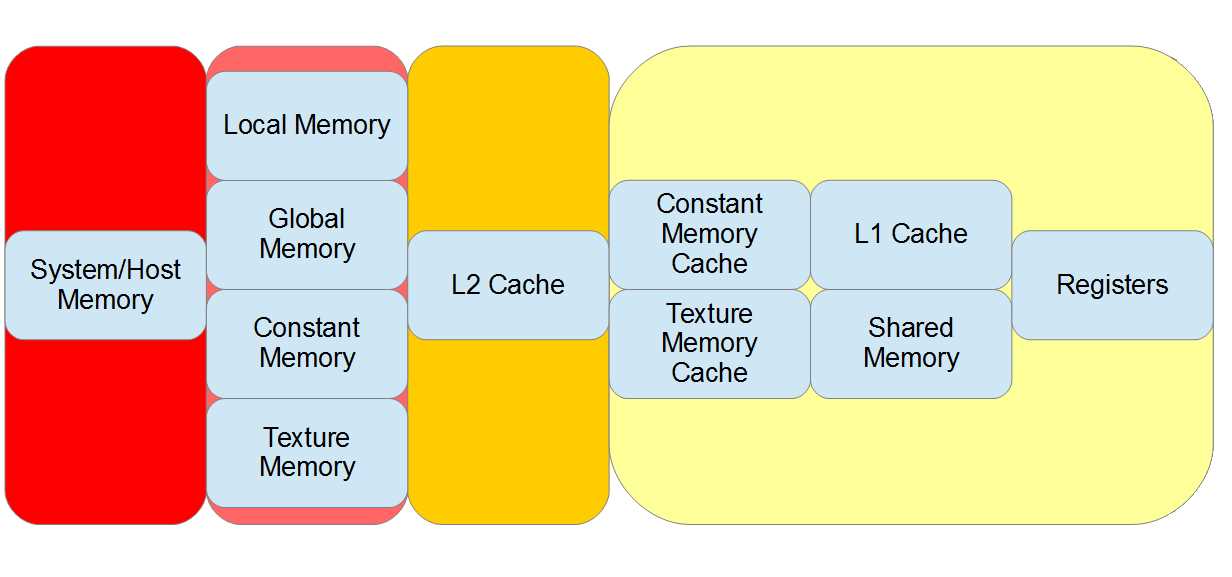
Figure 3.6: Memories ordered by access speed
The following table summarizes some of the key aspects of the CUDA memory spaces. Global memory speed is dependent on the current L1 and L2 cache usage and may not be slow at all.
Table 3.1: CUDA memories summary
Memory | Scope | Speed | Notes |
|---|---|---|---|
System | Host | - | Device cannot read/write system RAM. |
Registers | Thread | Very Fast | Limited supply. |
L1 Cache | Block/SM | Fast | Device-controlled, same memory as shared memory. |
L2 Cache | Grid | Slow | Device-controlled, all global memory r/w goes through L2. |
Shared | Block | Fast | User-controlled L1 cache memory. |
Texture | Grid | Slow/Fast | Uses global memory but has its own cache. |
Constant | Grid | Slow/Fast | Uses global memory but has its own cache, read only. |
Local | Thread | Slow | Used for local variables when registers cannot be used. |
- 1800+ high-performance UI components.
- Includes popular controls such as Grid, Chart, Scheduler, and more.
- 24x5 unlimited support by developers.