
AutoCAD Succinctly®

CHAPTER 5
Reference Objects
As you get experience in AutoCAD, you will soon realize that you have to repeat drawing and editing the same objects over and over. AutoCAD provides tools to empower the reuse of objects either in the same drawing or between drawings.
One way to reuse objects is by creating copies. You can copy any object in the drawing as many times as you like to reuse it anywhere in the drawing. Let’s assume that you create copies of a selection of objects a number of times, all over the drawing. Now assume that your client decided that part of those (repeated) objects need to be amended. If your selection was made of plain geometries (polylines, arcs, lines, etc.), you would have to find each of the copies and edit or replace the affected area for each of the instances.
In this chapter you are going to learn how to work with two great methods to reuse objects in a very effective way: blocks and external references (XREFs).
Blocks
A block is a single object composed other objects, and each element within the block may have its own property set.
Blocks are time and file-size savers. When a block is defined, AutoCAD stores it in an internal library in the current drawing, called Block Table. A block may exist in the drawing even if not used (inserted) anywhere, and if you create several instances of the block, either by re-inserting or by copying, all instances reference to the block library. If you edit a single block reference, all other blocks are equally updated.
Creating blocks
Command: BLOCK
Alias: B or BL
Before you create a block, first draw the element as you would do when creating any drawing. To illustrate creating a block, we are going to work on the Column Base drawing we created in previous chapters.
If AutoCAD is not already opened, open it now, and then open the drawing ColumnBase.dwg located in the Chapter 05 folder.
The drawing is composed of a blue polyline defining the column base outline and gray lines defining the column base transitions.
The elements are properly set on defined layers, but there are some practices that, although not required, become very handy when working with simple blocks like this:
- Set all objects to layer 0. The Layer 0 is a “magic” layer, and facilitates many operations when hiding or freezing layers.
- Set all properties as ByBlock. This will allow the user to change the block element’s appearance by changing the block properties, and if the block (object) properties are set as ByLayer, the block inherits the layer properties. If set as ByLayer, the block inherits the Layer Properties and changes in the block properties will not affect the block elements.
- Define a meaningful basepoint (insertion point).
Again, these are not rules, but become handy on low-density blocks. For more complex blocks, such as details, you may want to maintain all properties so that you can manage by other means.
Let’s change the objects properties for this block:
- Select all objects by Window or Window Crossing.
- From the Home Tab, Layers Panel, select Layer 0 from the layer list.
- From the Properties panel, change all properties to ByBlock (currently showing as ByLayer).
- Press Esc to unselect all objects.
- From the Layers panel, set the layer 0 as the current layer.
- From the Home tab, Block panel, click on the Create tool to open the Block Definition dialog.
- Enter Column Base in the Name field.
- In the Base point area, click Pick point.
- Press and hold Shift, right-click the mouse, and select Midpoint from the contextual menu.
- Click near the midpoint of the lowest horizontal line.
- In the Objects area, click Select objects.
- Select all objects defining the column base and press Enter.
- In the Select objects area, click on Convert to block.
- Click OK.
The source objects are now erased and the newly created block reference is inserted, in the current layer, where the source objects were before.
- Select the Block insertion.
- From the Home tab, Layers panel, change the block Layer to Column Base, then press Esc to clear selection. The block inherits the Layer properties.
- Save your drawing as MyBlocks.
Inserting blocks
Insert a block that exists in the current drawing’s Block Table
Command: INSERT
Alias: I or INS
Now that we have a block, we can insert additional instances of the block in the drawing, or you can copy the existing instances. For now, let’s see how to insert a block:
- Zoom out enough so that you may fit at least one more column base block in the drawing area.
- Set ColumnBase as the current Layer.
- From the Home tab, Block panel, click the Insert tool, or type I (or INSERT) and press Enter or the Spacebar.
- A list of the available blocks appears. Select the Column Base block. If no blocks are available in the drawing’s block table, the Insert dialog shows up, so you can load a drawing to insert as a block.
- A glyph denoting the block shows at the cursor, click anywhere in the drawing area to insert the block.
- Try copying the block as you did with the plant blocks in the previous chapter.
Insert an existing drawing as a block
Frequently, you will need to insert drawings from a file library that you have previously created or downloaded from a manufacturer’s website. Ideally the drawing to be inserted is a regular drawing and not a defined block in the drawing, as a new block definition containing the elements in the selected drawing is created upon insertion.
To insert an existing drawing as a block in the current drawing:
- From the Home tab, Block panel, click the Insert tool and then click More Options to open the Insert dialog.
- Click the Browse button and navigate to the location were you downloaded this book’s exercise files. In the Chapter 05 folder, select the drawing named sink.dwg and click Open.
- If needed, you can enter a new name for the block. Inserting a drawing with a name already existing in the Block Table will redefine existing blocks.
- Make sure that the Specify On-screen check box is checked so you can select the insertion point in the drawing area.
- Click OK.
- The block glyph appears in the crosshair cursor; click anywhere in the drawing to insert the block.
- The block is inserted in the current layer.
Edit blocks
Command: BEDIT
Alias: BE
You may need to make changes to the block. For example: I really didn’t like the way the column base transition lines are displayed, and they may plot to bold, depending on the plot style definition. We are going to edit the column base block so that the transition lines are gray:
- Select one of the column base block instances.
- Right-click the mouse and select Block Editor from the contextual menu.
The drawing area background color change to gray and the Block Editor contextual tab is loaded in the ribbon. You are now in the Block Editor mode.

Figure 100: Block Editor Contextual Tab
- Select all seven lines connecting across the column base (do not select the outline polyline).
- If the Properties palette is not visible, press Ctrl+1 to show the Properties palette.
- On the Properties palette, General properties, click the color dropdown menu and choose Select Color from the list.
- In the color text box, enter 9 and click OK to set the selected objects’ color.
- Press Esc to clear selection.
- Click Close Block Editor in the Block Editor contextual tab.
- Click Save to save the changes to Column Base.
- All instances of the block are updated.
Tip: When creating a block, you have the option to avoid the block to be exploded. This is quite helpful to avoid accidentally exploding blocks. This property can be changed from the Properties palette when on Block Editor mode.
Explode the sink block:
Command: X8 EXPLODE
Select objects: Select the sink block and press Enter or Spacebar.
The object is no longer a block.
Command: I8
The Insert dialog opens; select sink from the Name list and click OK.
Specify insertion point or [Basepoint/Scale/X/Y/Z/Rotate]: Select a point in the drawing area.
A new instance of the sink block is inserted because the sink block definition remains in the drawing’s Block Table.
Write block to file
You frequently will need to write a block to file so you can reuse it in future drawings. To write a block to a file, the selection does not have to be a block; it could be any selection set, including sets containing blocks and other non-block objects.
Command: WBLOCK
Alias: WB
Let’s write the Column Base block to a file:
- From the Insert tab, Block Definition panel, select Write Block, as shown in the following figure:

Figure 101: Write Block
- Select Block from the options.
- From the Block list, select Column Base.
- In the destination area, click the … button to show the Browse for Drawing File dialog box. Browse to a location of your preference.
- In the File name text box, enter My Column Base.dwg and click Save.
- Click OK to save the block.
The block is now saved, and you can reuse it in any future drawings.
Save and close the drawing.
Note: The resulting saved file does not contain a block; it contains the objects composing the selected block.
Tip: You can use Ctrl+C to copy objects from a drawing and Ctrl+V to paste in another drawing.
External references
An external reference (Xref) is similar to a block, but instead of saving the block in the current drawing’s block table, it is linked to an external file that could be in any folder in the file system. The Xref definition is saved in the Xref table and like with blocks, deleting an Xref instance from the drawing does not remove the file from the Xref table.
Xref is widely used when working with big files from different disciplines, and to facilitate design management. For example, in an architectural design, you can have a main floor plan that is an Xref into an interior design, structural, landscape, mechanical, or other plans.
Xref may be nested. You can attach an Xref that already contains other Xref attached, and this file could be an Xref for another drawing, and so on.
Because you can unload and reload an Xref on demand, its proper use may significantly improve drawing performance and design productivity, and also facilitates project management.
When an Xref is updated, all host drawings are automatically updated when closed, and if the host drawing is opened, a balloon notifies the user that the Xref was saved and needs to be updated.
You can freeze or turn layers off within the Xref.
Xrefs cannot be exploded unless bound (which turns the Xref into a block).
Xref types
- Attachment: An attachment Xref is loaded on all drawings where the attachment host file is inserted, independent of the number of levels.
- Overlay: An overlay is ignored when the drawing to which it is attached is then attached as an Xref to another drawing.
Insert external reference
Command: ATTACH
- Open the file FloorPlan.dwg located in the Chapter 05 folder.
- Make sure that the current layer is 0 (it’s a good practice to insert Xrefs on layer 0).
- From the Insert tab, Reference panel, click Attach.
- Navigate to the Chapter 05 folder.
- From the Files of type list (below in the dialog box), select Drawing (*.dwg).
- From the file list, select Survey.dwg and click Open to show the Attach External Reference dialog box.
- Make sure that Attachment is selected in the Reference Type area.
- In the Scale area, make sure that Specify On-screen is unchecked and that X, Y, and Z values are 1.00.
- In the Insertion point area, make sure that Specify On-screen is unchecked and that X, Y, and Z values are 0.00 (the Xref base point location).
- In the Rotation area, make sure that Specify On-screen is unchecked and that the angle is 0.00.
- Click OK to insert the Xref.
- From the Insert tab, Reference panel, click Attach.
- From the file list, select Electrical.dwg and click Open to show the Attach External Reference dialog box.
- Make sure that Overlay is selected in the Reference Type area.
- Click OK to attach the Electrical plan.
- Save the drawing.
- Open the Landscape.dwg file.
- Repeat the steps from 4 to 11 to attach the FloorPlan.dwg drawing.
- The Floor Plan and Survey drawings are now attached, but not the Electrical plan, because it is an overlay in the Floor Plan drawing.
- Save the drawing.
Edit external references
To edit an Xref, just open the file, make the changes, and save. The host drawing receives a notification every time an attachment is saved.
To quick-open an Xref:
- Click the Xref to select.
- Right-click the mouse to show the contextual menu.
- Select Open Xref to open the file.
- The Open Reference Files dialog is displayed, showing all attached and nested Xrefs.
- From the Reference Name list, select Survey, then click Open.
- The Survey drawing is loaded in a new drawing tab.
- Zoom and pan the drawing, and then save and close it (I’m not really willing to make changes, but AutoCAD recognizes any command as a drawing change).
- A notification balloon appears in the host drawings. Click Reload Survey to update the Xref.
- Save and close all drawings.

Managing external references
You can attach virtually any number of Xrefs, and you have full control over how and when they are visible, or if you need to detach any.
When you attach an Xref, AutoCAD shows the layers for each Xref prefixed by the Xref name, such as Landscape|L-Pool. You can change the layer properties and visibility without affecting the source, and any layer property change persists even if you reload the Xref, or across AutoCAD sections by default.
Tip: The layer visibility state is controlled by a system variable called VISRETAIN, and is drawing-persistent. When VISRETAIN = 1, the host drawing preserves layers’ property changes. When VISRETAIN = 0, the layers’ properties are restored every time the Xref is reloaded.
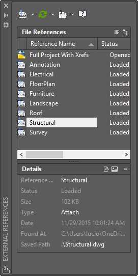
AutoCAD offers a tool to support managing Xrefs, called XRef Manager. Follow these steps to open the Xref Manager and manage Xrefs:
- If AutoCAD is not running, open AutoCAD.
- Open the Full Project With Xrefs drawing located in the Chapter 05 folder.
- In the command window, type XREF and press Enter to open the Xref Manager palette, as shown in Figure 102.
- In the File References list, select Annotation. Note that the Xref is highlighted in the drawing area.
- Right-click on Annotation. A menu appears with the commands available for the Xref.
- Select Unload. The Xref is unloaded and is no longer visible in the drawing area.
- Right-click on Annotation and choose Reload. The Xref is reloaded and visible in the drawing area.
- Right-click on Electrical and choose Detach. The Xref is detached from the drawing; it is no longer visible and cannot be reloaded.
- Right-click on Annotation and choose Bind.
- In the Bind Xrefs/DGN underlays dialog box, select Insert and click OK to bind the Xref.
- The Annotation plan is visible in the drawing area, converted to a block reference (you can explode the block as needed), and the Xref name was removed from the list.
Note: When binding Xrefs, the Bind mode preserves the layer, blocks, and other drawing elements’ prefixes (the Xref name), while Insert removes all prefixes.
- Click Attach DWG located at the top left of the palette.
- Find and attach the Electrical drawing as an attachment to the drawing.
Chapter summary
In this chapter, you learned how to work with blocks and external references, probably the most-used techniques to reuse drawings. Many design companies use blocks and Xrefs to define title blocks and detail sheets in drawings. We will accomplish this in Chapter 7.
- 1800+ high-performance UI components.
- Includes popular controls such as Grid, Chart, Scheduler, and more.
- 24x5 unlimited support by developers.