
AutoCAD Succinctly®

CHAPTER 1
Opening the Box
The Start page
After launching AutoCAD, it presents the Startup Window (Figure 1) from which you can start a new drawing using a template, open one of the last drawings, get notifications, or connect to Autodesk A360 (a project-based collaboration service for individuals, teams, and organizations), or send feedback about the product.
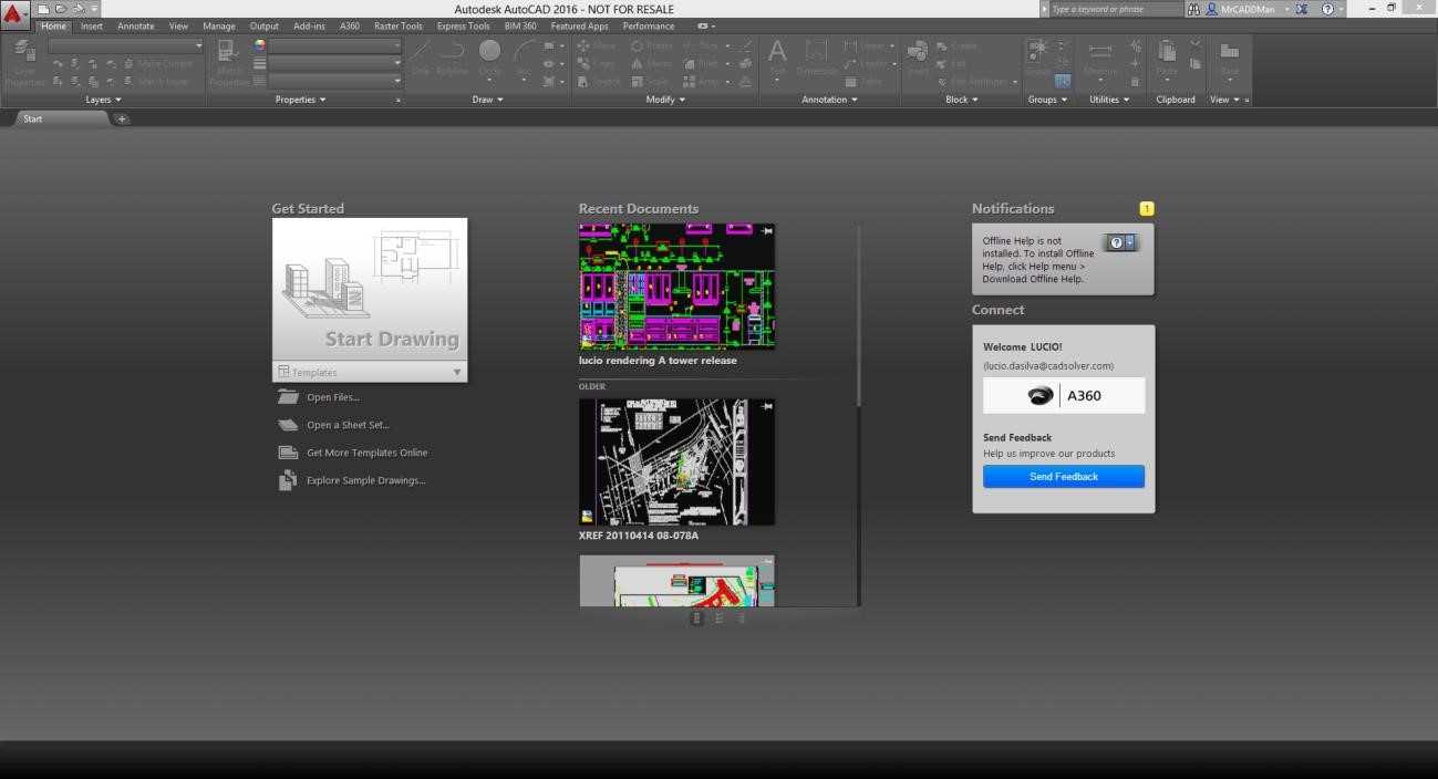
Figure 1: AutoCAD Startup Screen
The AutoCAD interface
The AutoCAD standard interface is composed of a number of items. The following figure shows the standard AutoCAD interface after launching AutoCAD and starting a drawing for the first time. Most interface components are floating or docked around the drawing area, and the most recent interface layout will persist after AutoCAD is closed.
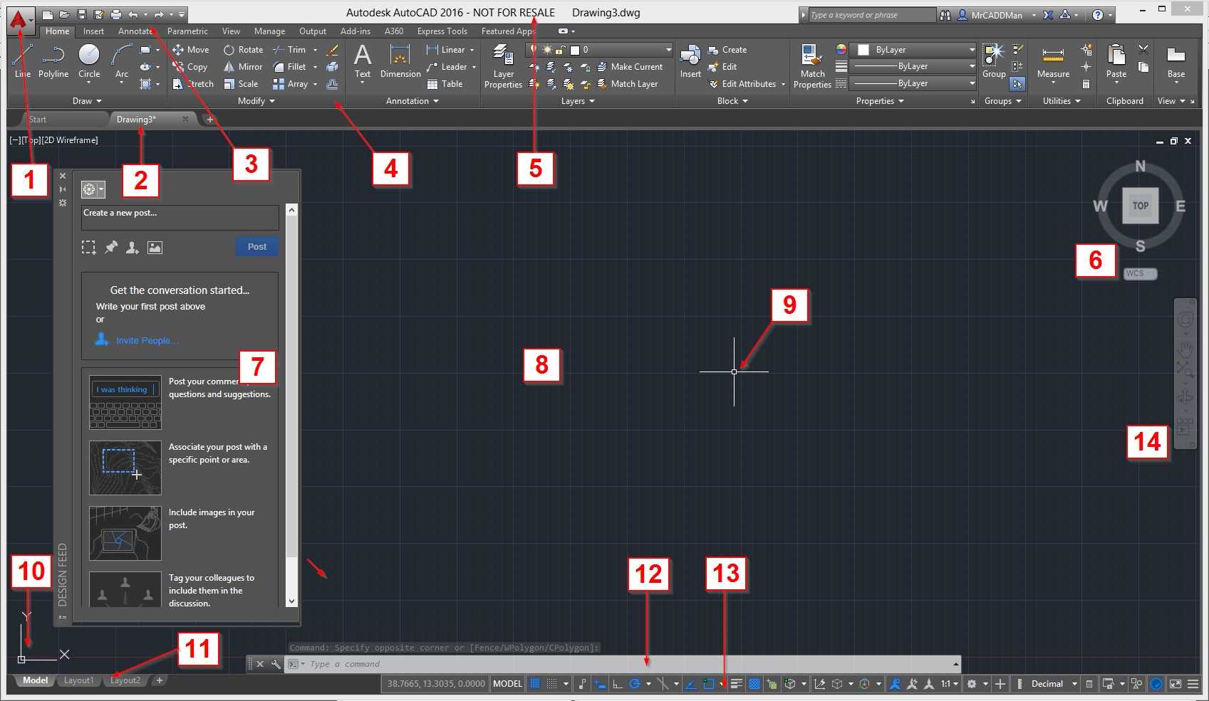
Figure 2: The AutoCAD Interface
The standard interface items are as follows:
- Menu Browser: From the Start menu, you can find commands for file management, publishing, and utilities.
- Drawing tabs: Shows all opened drawings and you can quickly switch between drawings with a single click.
- Quick Access Toolbar: Includes useful commands such as New, Open, Save, Print, Undo, and so on.
- The Ribbon: AutoCAD contains a ribbon across the top of the drawing area, including several tabs. You can access virtually all of the commands covered in this book from the Home tab.
- Title bar: Displays the product name and the active drawing name.
- View Cube: Widely used for 3D modeling.
- Tool Palette: AutoCAD contains several distinct tool palettes. The floating palette shown in Figure 2 is the “Design Feed.” To close a Tool Palette, click the X icon located at the top-left corner of the palette (it also could be located at the top-right corner, depending where it was last positioned.) If you have a tool palette currently open, you may close it, as we will not use it for the time being.
- Drawing Area: The large area, dark gray by default, is where your design happens. Initially the drawing area shows a grid that may be hidden, as you like.
- Crosshair Cursor: Creates and selects entities you create throughout the design process.
- User Coordinate System (UCS) Icon: Shows the current orientation of x and y vectors of the coordinate system. Every point of distance you enter is consistent with it.
- Layout Tabs: Consists of Model Space and Paper Space layouts. Model Space is where you create your design and Paper Space is your printing/plotting space. While you can create many Paper Space layouts, there can be only one Model Space layout.
- Command Window: This is where you communicate with AutoCAD, and where AutoCAD responds to your requests. You will learn more about the command window next.
- Status Bar: Contains numerous quick-access readings, toggle, and selection tools to help you working with the drawing.
Keyboard
As you become familiar with AutoCAD commands, you will be working more by typing commands and command aliases instead of selecting on the ribbon or toolbars. The keyboard is also of several shortcut commands that help you work with your drawing.
The most common keyboard uses are:
- Enter: Executes or ends a command to confirm an input. Pressing Enter at a blank command window will call the last command you run.
- Spacebar: Functions the same as the Enter key, but may have different results when attempting to finish a command, depending of the command you run.
- Escape (Esc) key: Finalizes or cancels commands.
- F1 key: Opens the Help window
- F2 key: If the command window is floating, it displays the extended command history; otherwise it opens the AutoCAD Text History Window. To show the AutoCAD Text History Window when the command window is floating, press Ctrl+F2.
- F3 key: Toggles object snap (osnap) on/off
- F7 key: Toggles the grid
- F8 key: Toggle orthographic (ortho) mode
- F9 key: Toggle snap to grid
- F10 key: Toggles polar mode
- F11 key: Toggles object tracking
- F12 key: Toggle dynamic input
Quick Access toolbar
![]()
The Quick Access toolbar is located, by default, on the top-left side of the application. It is fully customizable and the default tools are:
![]() New: Start a new drawing from a drawing template
New: Start a new drawing from a drawing template
![]() Open: Open an existing drawing
Open: Open an existing drawing
![]() Save: Save the current drawing
Save: Save the current drawing
![]() Save As: Save the current drawing with a new name
Save As: Save the current drawing with a new name
![]() Plot: Plot (print) the current drawing
Plot: Plot (print) the current drawing
![]() Undo: Undo the last command. AutoCAD can undo all up to the moment the drawing was created. When drawing is closed, the undo history is deleted, and a new history starts when the drawing is reopened.
Undo: Undo the last command. AutoCAD can undo all up to the moment the drawing was created. When drawing is closed, the undo history is deleted, and a new history starts when the drawing is reopened.
![]() Redo: Redo the last undone command, but only if immediately after the Undo command was used.
Redo: Redo the last undone command, but only if immediately after the Undo command was used.
The ribbon
The ribbon is located, by default, docked across the top of the drawing area. It’s composed of several tabs, which are composed of several panels, as shown in Figure 3. The ribbon can also be docked at the sides for floating (undocked) within the drawing area or on another monitor.
Panels that have a small triangle pointing down are expandable panels, and you can expand those by a single click on the panel title.
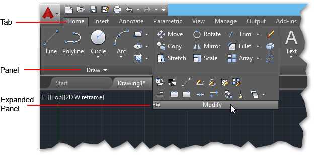
Figure 3: The Ribbon
Some ribbon panels allow access to a dialog box related to that panel. To show the dialog box, click the small arrow icon located at the lower-right corner of the panel (see Figure 4).
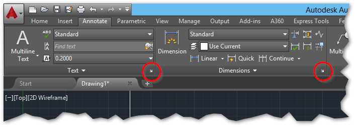
Figure 4: Dialog Box Launcher
A tooltip is displayed when you hover the mouse over a panel tool, and if you hold it a few seconds longer, a quick help window pops up, containing information about the respective command.
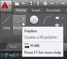
Figure 5: Tooltip
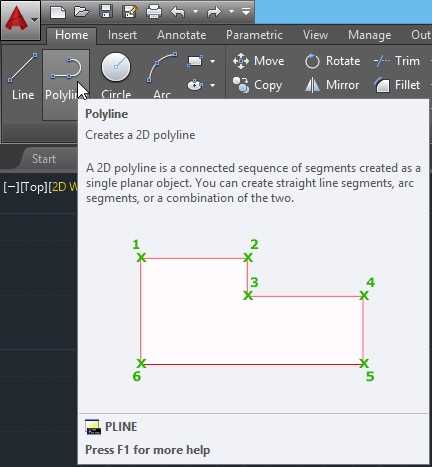
Figure 6: Quick Help
Contextual ribbon tabs
A contextual ribbon tab is a type of related ribbon tab that is displayed as a replacement for a toolbar or dialog box when you select certain objects or execute some commands, and automatically closes when you end the command or the object is unselected.
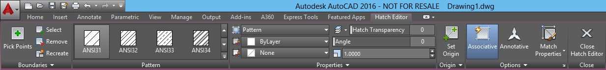
Figure 7: Contextual Ribbon Tab for the Hatches
The command window
The command window is the core of AutoCAD and it is, by default, located floating at the bottom of the drawing. You can place it at any location of your choice by clicking the bar on the left of the window and dragging (Figure 8). When you get closer to the top or bottom of drawing area, the command window will attempt to dock at the location. This characteristic is similar for tool palettes, which can be floated or docked to the sides.
![]()
Figure 8: Command Window
When you start typing a command, several possibilities are available to choose from, as shown in Figure 9. You can select your choice by clicking it or using the keyboard arrows to select the proper command, and then press Enter or the Spacebar.
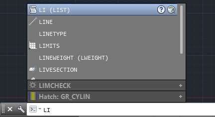
Figure 9: Command Auto Complete
Mouse
It’s a good idea to have a mouse with left and right buttons and a wheel. A good mouse can save you a lot of of time at the end of your project.
The following list describes how to use mouse keys:
- Left button: Used for entity selection as well as marking coordinate points.
- Right button: Opens the contextual menu matching the current selected entity, if any.
- Wheel:
- Roll up: Zoom in
- Roll down: Zoom out
- Double-click: Zoom to the extension of your drawing
- Press, hold, and drag: Pan the drawing
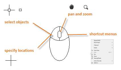
Figure 10: The Mouse
Create a new drawing
There are a few ways to start a new drawing. If you just launched AutoCAD, you can start a new drawing from the Start page, previously shown in Figure 1. Click Start Drawing (Figure 2) to begin a new drawing. This will start a new, blank drawing based on the AutoCAD standard template.
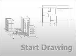
Figure 11: Start Drawing at The Start Page
Another way to start a drawing is by clicking New in the Quick Access toolbar, as shown in the following figure.
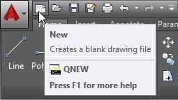
Figure 12: Quick Access Toolbar
Clicking New opens the New Drawing dialog window (Figure 12), from which you can select the template you would like to use to start your drawing.
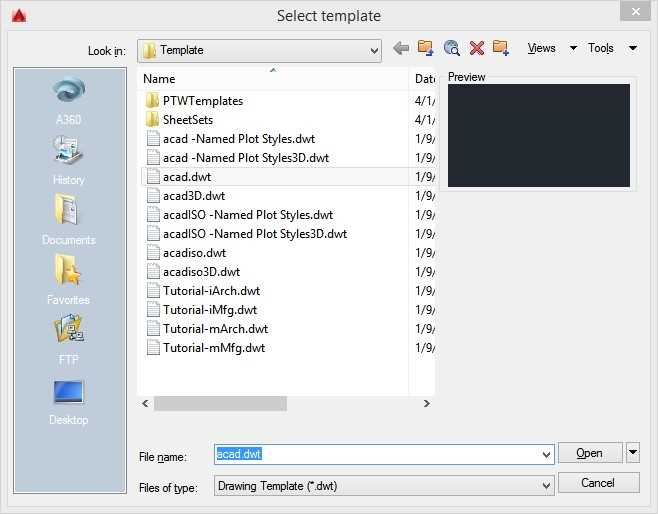
Figure 13: New Drawing Dialog
If you work on imperial drawings, where it is assumed that you work in inches, you should use the acad.dwt (or acadlt.dwt if you are working in AutoCAD LT).
For metric units, it is assumed that units are millimeters; you may use acadiso.dwt (or acadltiso.dwt in AutoCAD LT).
Note: For simplification and generalization, all drawings in this book are based on the acad.dwt template.
You may also start a new drawing by selecting a template right from the Start page, as shown in Figure 14.
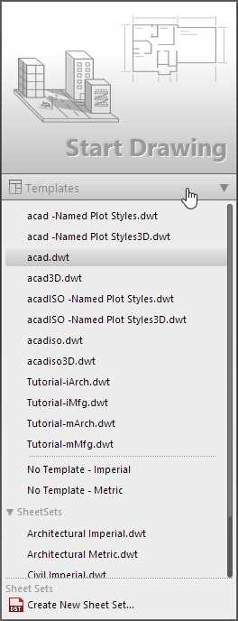
Figure 14: Create a new drawing using a custom template
All objects created in Model Space should be created in full-sized, real-world units (1:1 scale). Entering 10 units as distance means that it could be 10 inches, 10 millimeters, or any other unit that you specify, such as meters or feet. It’s important to remember that you cannot mix units once you have started the drawing. If you started a drawing assuming that 1 unit = 1 mm., you cannot enter 5 cm. as distance; instead you will have to enter 50. You do not enter the actual units unless you are using the Architectural measurement type; then you may enter values such as 6’-6” and AutoCAD will interpret that as 78 drawing units.
Drawing units
You can choose what unit of length you want use by running the UNITS command. From the Menu Browser, select Drawing Utilities, and select the Units option. Or, from the command window, enter UNITS and press Enter or the Spacebar. The Drawing Units dialog window opens, as shown in Figure 15:
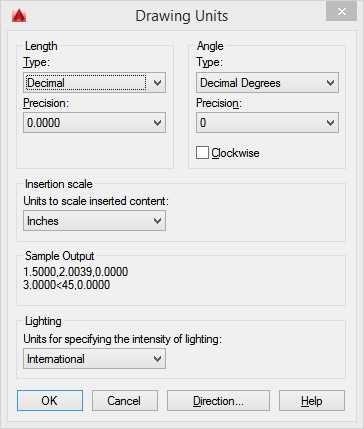
Figure 15: Drawing Units Dialog
The Drawing Units dialog components are:
- Length Type (or Format): Determines how lengths are shown. For example, a decimal length of 6.5 can be set to display as a fractional length of 6-1/2 instead.
- Precision: Determines the decimal accuracy of a length. For example, a decimal length of 6.5 can be set to be displayed as 6.50, 6.500, or 6.5000.
- Angle Type: Determines the unit of the angle. You may choose from Degrees Minutes and Seconds (Deg/Min/Sec), Grads, Radians, or Surveyor’s Units (e.g. N 10d25’10” E). Decimal Degrees is the default.
- Clockwise: By default, angles are measured counter-clockwise; check this box if you need to revert.
- Insertion Scale Units: Automatically scales inserted materials with other units to the correct unit. For example, if you are working in a drawing in which the unit is set to millimeters and insert a drawing set as inches, the resulting inserted objects are automatically resized with a scale factor of 25.4 (1 inch = 25.4 mm.).
- Sample Output: Displays an example of the current settings for units and angles.
- Lighting: On photorealistic renderings, it controls the unit of measurement for the intensity of photometric lights in the current drawing.
If you plan to work in feet and inches, set the Length type to Architectural, and then when you create objects, specify their lengths in feet and inches (e.g. 3’5-3/4”). If you plan to use metric units, leave the Length type set to Decimal. Changing the unit format and precision does not affect the internal precision of your drawing. It affects only how lengths, angles, and coordinates are displayed in the user interface.
Display settings
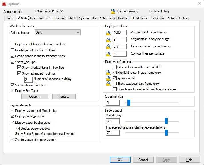
Figure 16: Options dialog with Display tab active
The default AutoCAD display settings are a dark user interface, a dark drawing area in model space, and a white paper space. AutoCAD is fully customizable, so you can change the colors according to your preferences.
To change display settings, run the OPTION command by clicking the Options button located at the bottom of the Menu Browser or by typing OP at the command window and pressing Enter or the Spacebar.
This will open the Options dialog window containing a few tabs on standard AutoCAD (see Figure 16). Click on the Display tab to view the display settings options. I am not covering all items available in the Options dialog nor in the Display tab, as they will not affect the contents of this book. At this point, we are only to change how to adjust colors and Crosshair Cursor settings.
Under the Window Elements area, you find the Color scheme with two options: Dark and Light. This will change elements of the user interface, such as ribbon, palette, and menu colors. Dark is the AutoCAD default, and if you prefer a light gray interface, choose Light on the drop-down list.
To change drawing environment colors, click on the Colors… button located at the bottom of the Window Elements area to open the Drawing Window Colors menu, as shown in Figure 17. To change the space color, select 2D model space in the Context list, Uniform background in the Interface element list, and select the color of your choice in the Color list. You can safely change the colors and easily reset them by clicking the following buttons:
- Restore current element: Reset the default colors of the selected item in the Interface Element list.
- Restore current context: Restore the default colors of the selected item in the Context list. This will reset all items in the Interface Element list.
- Restore all contexts: Restore the default colors for all Contexts and Elements.
- Restore classic colors: This button will set all colors to legacy AutoCAD colors.
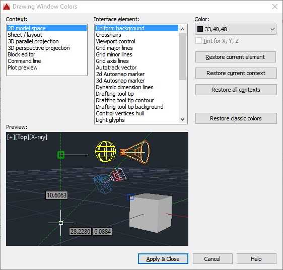
Figure 17: Drawing Windows Colors
Click Apply & Close to apply your changes and close the dialog box, or Cancel to close the dialog without applying any changes, and return to the Options dialog.
Note: Changing the uniform background color to white automatically changes the display color of white objects to black, and vice-versa. Actually, white objects print and plot in black by default. The crosshair cursor automatically adjusts its colors.
The Crosshair size slider changes the size of the crosshair cursor in the drawing area. It goes from 1 to 100, where 100 makes the crosshair axis cover 100 percent of the drawing area. The default value is 5.
Click OK to close the dialog and apply the changes, or Cancel to close without making changes.
- 1800+ high-performance UI components.
- Includes popular controls such as Grid, Chart, Scheduler, and more.
- 24x5 unlimited support by developers.