
AutoCAD Succinctly®

CHAPTER 4
Managing the Drawing
Selecting objects
Whenever you need to modify your drawing, you need to select the objects you are willing to change. AutoCAD includes a number of methods to help selecting objects. You can select any object that is not in a frozen or locked layer.
You can select objects before or after running a command. If you run a command while no object is selected, AutoCAD presents the following prompt in the command window:
Select objects:
You can select objects by simply clicking on it or using either a Window, a Window Crossing, or a Lasso without additional prompts.
Window
Selects all objects completely inside a rectangular area defined by two points selected from left to right.
To start selecting, click in the drawing area to the left (above or below) the object or objects you are willing to select (do not hold the mouse button) and move the mouse to the right to create a rectangular area around the object or objects. The selection window is filled in blue with a solid border.
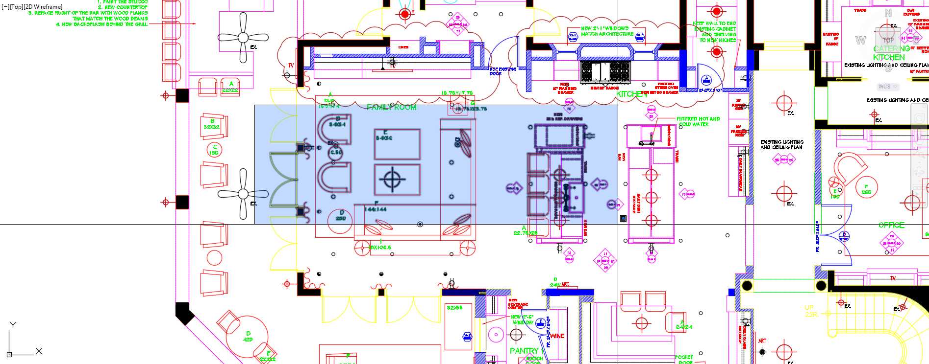
Figure 83: Window selection
Window Crossing
Selects all objects that are inside or crossed by a rectangular area defined by two points selected from right to left.
The selection window is filled in green with a dashed border.
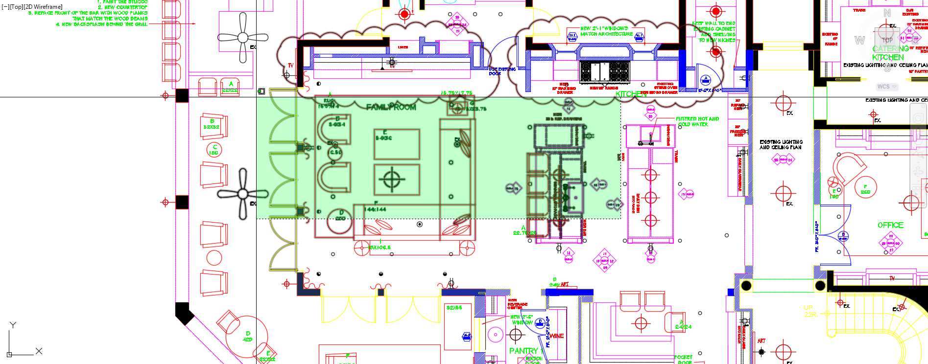
Figure 84: Crossing Selection
Lasso
You can lasso select objects by holding the left button of the mouse and drawing around the objects you are willing to select. Similar to the Window and Window Crossing selection, start dragging the mouse from left to right to select all objects that are completely inside of the lasso boundaries. Starting from right to left (Crossing Lasso) will select all objects inside the lasso as well those crossed by the lasso boundaries.
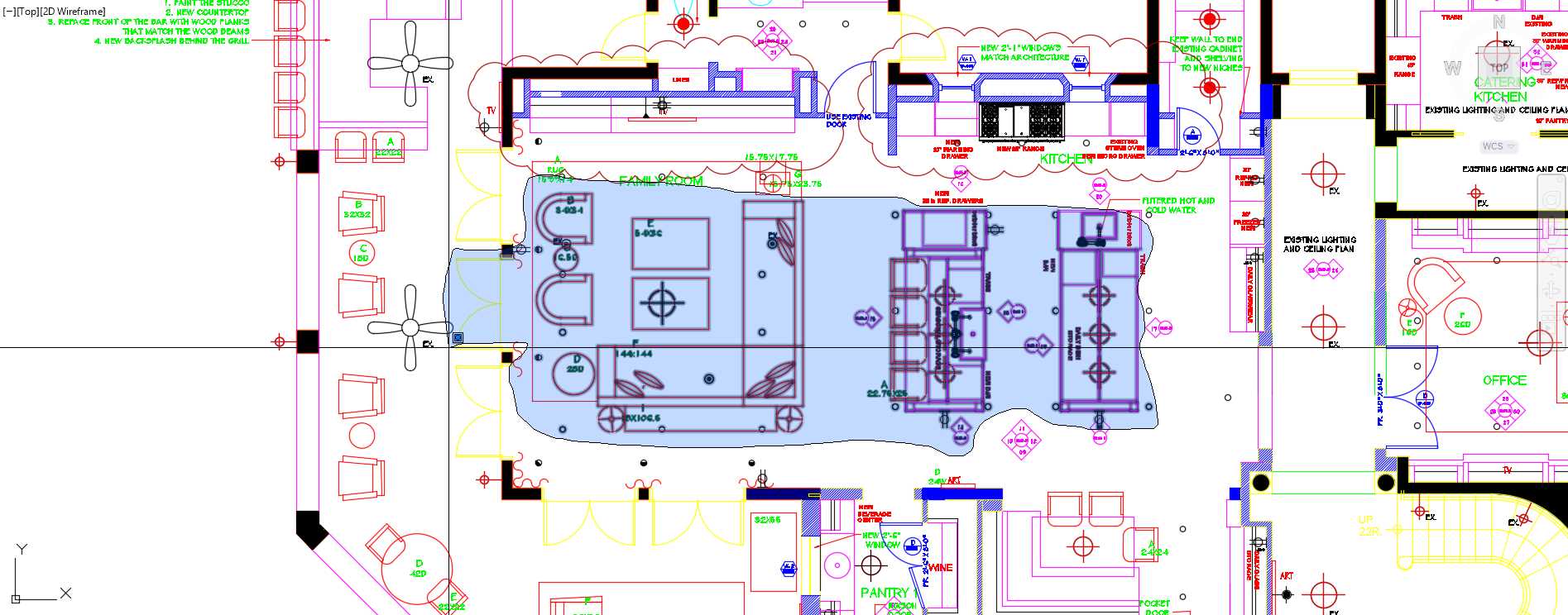
Figure 85: Lasso Selection
Tip: You can deactivate the Lasso Selection mode from the Options Dialog, Selection Tab. Uncheck the “Allow press and drag for Lasso” checkbox.
Command prompt options
All: Selects all objects in the drawing, including objects on other spaces (except those on frozen or locked layers.)
Select objects: all8
6110 found (204 duplicate), 5217 total
893 were not in current space.
Last or L: Select the last created object in the active drawing space, assuming the object’s layer is neither frozen nor locked.
Select objects: L
1 found
Crossing: Same as Window Crossing, but allows crossing selection to any direction.
WPolygon or WP (Window Polygon): Select all elements that are completely inside of a polygonal boundary defined by points.
Select objects: WP
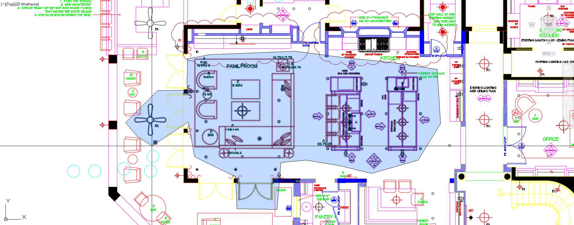
Figure 86: WPoligon Selection
CPolygon or CP (Crossing Polygon): Select all objects inside and crossed by a polygonal boundary defined by points.
Select objects: CP
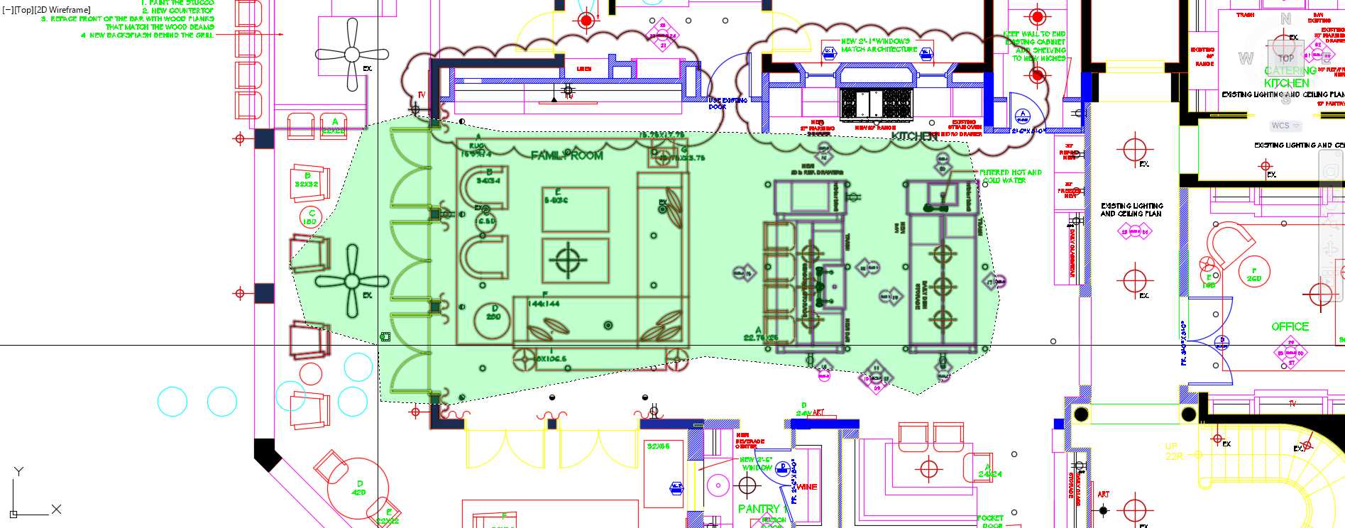
Figure 87: CPolygon Selection
Fence of F: Similar to CPolygon, except that only the objects crossed by the boundary are selected.
Select objects: F
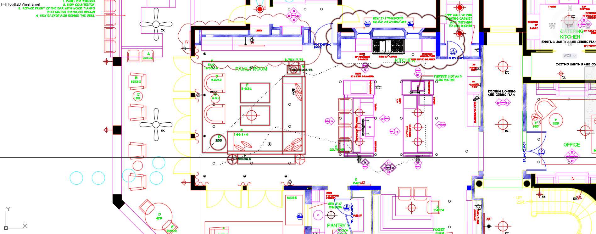
Figure 88: Fence Selection
Select Similar
Select Similar allows the user to select all objects similar to the one previously selected. Select Similar is very helpful if you want to select, for example, a group of matching blocks in the drawing.
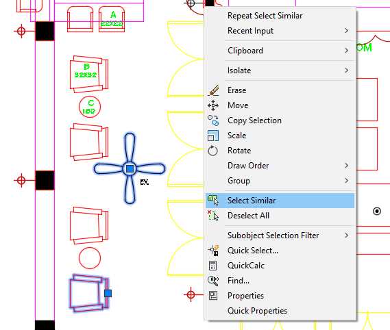
Figure 89: Select Similar
To select similar objects, first select the object or objects to use as reference, then right-click the mouse to show the contextual menu, and click on Select Similar, as shown in Figure 89.
Managing layers
You became familiar with layers and the Layer Properties Manager in Chapter 2. Now it’s time to review the power of using layers in AutoCAD. Most graphic design software available has a method to organize the drawing in layers.
You can use layers to control the visibility of the objects in the drawing or output as well as set properties like color, line type, line weight, and transparency. When an object is created, it inherits the properties associated to the layer on which is was created, although you can override object properties as needed. When you see an object property shown as BYLAYER, it means that that property is inherited from the object’s layer.
To open the Layer Property Manager window:
From the Home Tab, Layers Panel, click on the Layer Properties tool.
Command: LAYER
Alias: LA
Layer list
The layer list in the Layer Property Manager window shows the list of the layers in the drawing and the properties. You can sort the list by clicking in the column header.
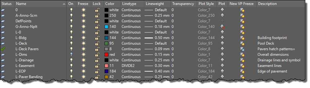
Figure 90: Layer List
Tip: Press and hold the Shift key to select a continuous group of layers, or press and hold the Ctrl key to select alternating layers.
The layer list has the following columns:
- Status: Shows an icon depicting the layer status. The layer with a green check mark is the current layer. To set another layer as current, double-click the layer status or layer name.
- Name: Shows the layer name. To rename a layer, select the layer and press F2.
- On: Turns the selected layers on or off. Turn a layer off to make the layer invisible in the display as well when plotting. Objects in an “Off” layer participate in the regeneration process and some selection methods.
- Freeze: Frozen layers are invisible, not plotted, and are ignored when selecting objects and regenerating the drawing. This improves performance and regeneration time on complex drawings.
- Lock: Objects in a locked layer cannot be modified, although you may add new objects in the layer.
- Color: Defines the layer’s color.
- Linetype: Defines the layer’s linetype.
- Lineweight: Sets the layer lineweight.
- Transparency: Sets the layer’s transparency level from 0 to 90, where 0 is completely opaque.
- Plot Style: Allows selecting a plot style for the layer. This option is disabled if the drawing plot style policy is a color dependent plot style.
- Plot: Sets the visibility of objects when plotting. When set as no-plot, objects are displayed on the screen but not in plots.
- New VP Freeze: Defines if the layer is visible on newly created viewports on layout tabs.
- Description: You can enter a friendly description for the layer. This field is optional, and you and edit by pressing F2.
Layer panel tools
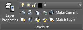
Figure 91: Layer Panel
The Layer panel is located in the Home tab, by default, and consists of the following tools:
![]() Layer Properties: Open the layer property manager from where you can add new layers, edit existing layers’ properties, manage layer filters and states, or remove empty layers.
Layer Properties: Open the layer property manager from where you can add new layers, edit existing layers’ properties, manage layer filters and states, or remove empty layers.
Layers List: Show the current (active) layer. All new objects are assigned to this layer. You can also activate another layer from this list or change the layer properties of an object selection. You can also change the layer state from this list.
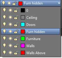
Figure 92: Layer List Dropdown
Note: Make sure that you have no objects selected if willing to activate another layer. Changing the layer in the list with one or more objects selected will assigned the objects to the selected layer.
![]() Off: Turn off the layer by selecting objects. Use this command to clear the view and facilitate reading the drawing or plots.
Off: Turn off the layer by selecting objects. Use this command to clear the view and facilitate reading the drawing or plots.
![]() Isolate Layers: This command turns off all layers except those from selected objects. Very helpful when willing to work only with certain objects. For example, you may want to work only on walls, windows, and doors and hide all dimensions, ceiling plans, notes, etc. You restore the layer state with the Layer Un-isolate command.
Isolate Layers: This command turns off all layers except those from selected objects. Very helpful when willing to work only with certain objects. For example, you may want to work only on walls, windows, and doors and hide all dimensions, ceiling plans, notes, etc. You restore the layer state with the Layer Un-isolate command.
![]() Freeze: Freezes layers by selecting objects.
Freeze: Freezes layers by selecting objects.
![]() Lock: Locks layers by selecting objects. This is useful when you need to see and snap to objects in a layer without risking accidentally modifying or deleting these objects.
Lock: Locks layers by selecting objects. This is useful when you need to see and snap to objects in a layer without risking accidentally modifying or deleting these objects.
![]() Make Current: Make the selected object the current (active) layer.
Make Current: Make the selected object the current (active) layer.
![]() Layer On: Turn all layers on in the drawing.
Layer On: Turn all layers on in the drawing.
![]() Un-Isolate Layers: Restore the layer state as prior to the last Layer Isolate command.
Un-Isolate Layers: Restore the layer state as prior to the last Layer Isolate command.
![]() Thaw All Layers: Thaw (unfreeze) all layers in the drawing. It does not thaw layers frozen in Paper Space layouts.
Thaw All Layers: Thaw (unfreeze) all layers in the drawing. It does not thaw layers frozen in Paper Space layouts.
![]() Unlock: Unlock layers by clicking on objects.
Unlock: Unlock layers by clicking on objects.
![]() Match Layer: This command allows the user to match another objects’ layer to a selected object’s layer.
Match Layer: This command allows the user to match another objects’ layer to a selected object’s layer.
Hands on layers
In this topic we are going to work on an existing file to edit layers, hide and isolate layers and objects, as well as editing existing objects. Please proceed with the following steps:
- Open AutoCAD, if not already opened.
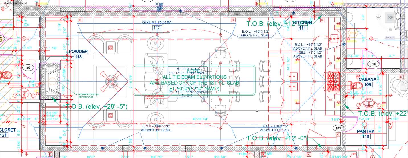
- Open the First Floor Plan drawing located in the Chapter 04 folder. This drawing is an architectural plan including a basic survey and landscape plan.
The drawing is very difficult to read, so let’s turn off some layers to make it easier to read.
- Zoom closer to the center of the house so that the Great Room fits in the drawing area.
- In the Home tab, Layers panel, click the Off tool (see the Layer Panel Tools topic earlier in this chapter).
- Randomly click some objects to turn their assigned layers off. If you accidentally turned off a layer, enter U and press Enter to restore the last layer visibility. You can pan and zoom with the mouse wheel as needed without interrupting the command.
- Press Enter, Spacebar, or Esc to finish the command.
Note: You may receive an alert in the command window informing you that you are attempting to turn the current layer off. You have to confirm the action. It is not recommended to turn the current layer off, as you may create new objects that will be invisible until you turn the layer on.
To turn all layers back on, click the Layers On tool in the Layers Panel, or type LAYON in the command window and press Enter or the Spacebar. All layers that were turned off are now on.
You can also turn layers on or off directly from the Layer Properties window or from the Layer List in the Layers panel; a gray light bulb indicates that the layer is off, and a yellow light bulb indicates that the layer is on.
Open the Layer Properties Window and turn off the following layers:
A-Anno-Det-TAG, A-Anno-Dims, A-Anno-E-Dr-TAG, A-Anno-Elev-TAG-48, A-Anno-Mas-Dim, A-Anno-Mas-Slab-Elev, A-Anno-Mas-Text, A-Anno-TieB-Txt, A-Anno-Win-TAG, A-Clng-Circ, A-Clng-Head, A-Clng-Lite, A-Flor-Case, A-Furn-Free, A-Grid-Cntr, A-Roof-Lines, A-Site-Hatch, A-Site-Vegn, A-Str-Slab-Edge, A-Str-Tie-Beam, A-Str-TieBm-Htch, S-Anno-Site-spot elev, S-Anno-Site-Text, and S-Site-Misc.
Close the Layer Properties if needed.
Pan and zoom to the Pool Area and click the Isolate tool button in the Layers Panel, or type LAYISO in the command window and press Enter or the Spacebar.
Tip: By default, the LAYISO command (Isolate tool) locks and fades the layers of unselected objects. To make it turn the layers off, enter S in the command window, press Enter, type O, and press Enter. This setting is preserved for new drawings or AutoCAD sections until you change it again.
Select any line within the pool and press Enter.
Click the Unisolate tool button in the Layers panel, or type LAYUNISO in the command window, and press Enter or the Spacebar, to restore the previous state.
Save your drawing as My First Floor Plan and close the drawing.
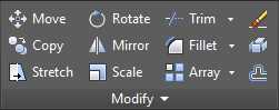
Modifying objects
AutoCAD offers a number of tools to support reusing and modifying existing objects. Most of these tools are located in the Modify Panel (Figure 93) in the Home tab.
Common prompt options:
- Select objects: Select the objects to be modified.
- Base point: Select a point to use as reference point
Move
Move selected objects to a new location.
Command: MOVE
Alias: M
Copy
Create a copy of selected objects in a new location.
Command: COPY
Alias: CP or CO
Prompt options:
- Mode: Change the option to allow creating many (Multiple) copies in a single command, or to finish the command after one copy is created (Single).
- Array: Creates a linear array with an equally spaced number of objects.
- Number of Items to Array
- Second Point: Defines a distance and direction for the array relative to the base point. The first element in the array is positioned at the specified distance and the remaining elements are equally distributed at this given distance.
- Fit: Create a number of copies of the object equally spaced in order to fit a selected distance.
Rotate
Rotates one or more objects around a base point to an absolute angle.
Command: ROTATE
Alias: RO
Prompt options:
- Rotation Angle: Defines the angle of rotation where the rotation axis passes through the selected base point and matches the current UCS orientation.
- Copy: Creates a copy of the selected objects for rotation.
- Reference: Allows the user to specify a new angle to use as the base angle. The object is then rotated in reference to the new selected angle.
Offset
Create a copy of a selected object parallel or concentric to the original object.
Command: OFFSET
Alias: O
Prompt options:
- Offset Distance: Specify the distance from the source object.
- Exit: Exits the command.
- Multiple: Repeats the offset operation using the current offset distance.
- Undo: Reverses the previous offset.
- Through: Creates an object passing through a specified point.
Stretch
The Stretch command allows you to modify a selected object by stretching the points enclosed by a crossing window or other crossing selection method described in the Selecting Objects topic earlier in this chapter.
Command: STRETCH
Alias: S
Mirror
Creates a new objects mirrored from a selection of objects.
Command: MIRROR
Alias: MI
Prompt options:
- Specify first point, second point of mirror line: Defines a line that acts like a mirror. All selected objects are mirrored through the mirror line. The distance from the mirrored object’s points to the mirror line is the same as the source object’s points to the mirror line.
- Erase source objects: Option to keep or remove the source object.
Scale
Resizes one or more objects by specifying a base point and the scale factor. A negative scale factor mirrors the selection.
Command: SCALE
Alias: SC
Trim
The Trim command allows the user to trim objects at a selected trimming boundary. To use all existing objects as trimming boundaries, press Enter at the first prompt for object selection. The Trim command is useful to trim lines at a wall opening, for example.
Command: TRIM
Alias: TR
Tip: Using Shift + Click when selecting an object to trim will extend the object rather than trimming it.
Extend
Extends selected objects to touch a previously selected boundary. This command works similarly to the Trim command.
Command: EXTEND
Alias: EX
Tip: Using Shift + Click when selecting an object to trim will trim the object rather than extending it.
Fillet
Create a rounded corner from two objects. By default, Fillet automatically trims or extends open objects (lines, arcs, open polylines) as needed.
Command: FILLET
Alias: F
Prompt options:
- Undo: Undo the previous fillet corner in the command section.
- Polyline: Round all the corners of a polyline with the specified fillet radius.
- Radius: Sets fillet radius.
- Trim: Defines if the filleted segments are to be trimmed.
- Trim. Selected segments are trimmed to meet the endpoints of the fillet. This is the default setting.
- No Trim. Selected segments are preserved and are not trimmed.
- Multiple: Allows the user to create multiple filleted corners on a single command run.
Chamfer
Creates a beveled corner from two non-parallel linear segments.
Command: CHAMFER
Alias: CHA
Prompt options:
- Undo: Undo the previous chamfered corner in the command section.
- Polyline: Chamfers all the corners of a polyline with the specified distances.
- Distance: Sets chamfer distances.
- Specify first chamfer distance: The chamfer distance on the first selected line.
- Specify second chamfer distance: The chamfer distance on the second selected line.
- Angle: Sets the chamfer distance from the selected element intersection point and the angle from the first segment.
- Trim: Defines if the filleted segments are to be trimmed.
- Trim. Selected segments are trimmed to meet the endpoints of the chamfer. This is the default setting.
- No Trim. The chamfer segment is created but the original selected segments are preserved.
- Multiple: Allows the user to create multiple chamfered corners on a single command run.
Polyline edit
This command allows the user to edit a polyline or create a new polyline from existing lines, arcs, and splines.
Command: PEDIT
Alias: PE
Prompt options:
- Close: Close the polyline by creating a segment connecting the last point to the first point in the polyline.
- Open: Remove the segment closing the polyline.
- Join: Allows the user to add additional elements to the polyline. The polyline must be open and the elements to be added must share end or start points.
- Width: Set the polyline width. This is a scalable value. If the width value is greater than zero, the output width is scaled to match the plot scale.
- Edit vertex: Allows the user to edit each vertex in the polyline individually.
- Fit: Create a curved polyline with arcs connected on each polyline vertex.
- Spline: Converts the polyline to spline-fit polyline where each vertex of the polyline is a spline control point.
- Decurve: Straighten a curved polyline. All curved segments become linear segments.
- Ltype gen: Useful when a line type other than continuous is assigned to the layer or polyline. When this feature is on, the polyline line type is generated continuously without re-staring on each segment.
- Reverse: Reverses the vertex order of the polyline.
- Undo: Undo each action through the polyline edit section.
Array
The Array command creates copies of objects evenly spaced and can be created as rectangular form, radial (polar), or following a path. The array tools are found in the Modify panel of the Home tab, as shown in the following figure:
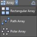
Figure 94: Array Tools
Command: ARRAY
Alias: AR
The ARRAY command has the following options:
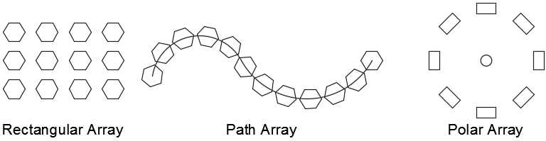
Figure 95: Array Types
The following options are common to all array creation methods:
- Associative: Specifies whether the arrayed objects are associative or independent.
- Yes: The array is created as a single object containing multiple instances of the source objects. Associative array allows editing the array after the command is completed through the Properties Palette of the Array Contextual Tab, as well as editing the source objects.
- No: The resulting array is composed with independent objects, cannot be dynamically edited, and editing the source objects will not affect the others.
- Base point: Allows the user to set the base point and base point grip of the array.
- Exit or Close Array: Ends the command.
Rectangular
Rectangular arrays are composed with rows and columns. The alternative command to create rectangular arrays is ARRAYRECT.
You can create arrays by selecting objects before or after calling the command. After the selection of objects is completed, the Array Creation contextual tab is displayed in the ribbon, as shown in Figure 96
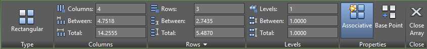
Figure 96: Rectangular Array contextual tab
The options to create a rectangular array are:
- Columns: Specify the number of columns in the array. Columns are created following the X direction of the current UCS.
- Between: Sets the distance between centers of the elements in the array in the X direction of the current UCS.
- Total: Sets the total length of the array in the X direction of the current UCS.
- Rows: Specify the number of rows in the array. Rows are created following the Y direction of the current UCS.
- Between: Sets the distance between centers of the elements in the array in the Y direction of the current UCS.
- Total: Sets the total length of the array in the Y direction of the current UCS.
- Levels: Specify the number levels in the array. Levels are created following the Z direction of the current UCS.
- Between: Sets the distance between centers of the elements in the array in the Z direction of the current UCS.
- Total: Sets the total length of the array in the Z direction of the current UCS.
Path
Create an array of objects evenly spaced along a selected path. The alternative command to create rectangular arrays is ARRAYPATH.
To create a path array:
- Click on the Path Array tool
- If you had no objects selected prior calling the command, select the object(s) you want to distribute (source object) along the path. Press Enter to complete the selection.
- Select the distribution path. The path can be a line, polyline, 3D polyline, spline, helix, arc, circle, or ellipse.
The Path Array Creation contextual tab is activated in the ribbon as shown in the following figure:

Figure 97: Path Array Creation panel
The options to create a path array are:
- Method: Controls how to distribute items along the path.
- Measure: Distributes the objects along the path at points equally spaced by the entered distance.
- Items: Specifies the number of instances to be distributed
- Divide: Distributes the objects along the path to fill the entered distance. The distance between items is calculated.
- Between: Specifies the distance, center to center, of the objects to be instanced along the path.
- Tangent direction: Specifies how the objects in the array are aligned relative to the starting direction of the path. Select two points that defines the tangent line of the first element in the array that is to be distributed throughout the path.
- Rows: Specifies the number of rows in the array, the distance between them, and the incremental elevation between row.
- Number of rows: Defines the number of rows along the path.
- Distance between rows: Identifies the distance between each row evenly distributed.
- Total: Defines the total distance between the first and last rows.
- Align items: When set, the items in the array are rotated to follow the path, otherwise the items maintain the same orientation as the source object(s).
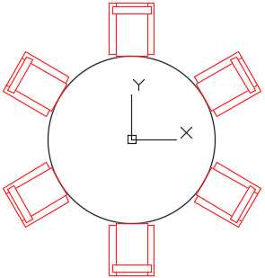
Polar
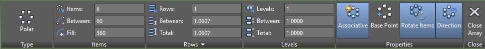
Polar arrays repeat the selected objects by rotating around a selected point, as shown in the following figure:
Explode
Converts the selected objects to the next primitive level. For example, exploding a polyline converts the polyline to regular independent line and arc segments.
Command: EXPLODE
Alias: X
Erase
The Erase command deletes the selected objects from the drawing. It does not copy the object to the clipboard to be pasted somewhere else.
Command: ERASE
Alias: E
Shortcut: DEL key
Tip: The OOPS command restores the last erased objects independently of how many commands were executed after they were erased.
Working with grips
If you select objects when no command is running, the selected objects display small, solid-filled squares on each vertex node, or base point of the object (Figure 98). These squares are called grips (a blue grip is called a cold grip), and you can edit the object by dragging the grip stretch, move, rotate, scale, or mirror objects quickly. More edit options are available, depending on the type of object. The action you choose to execute is called a grip mode. I personally edit objects more frequently using grips than any other method.
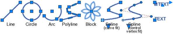
Figure 98: Grips on Selected Objects
Note: Grips are not displayed on objects that are on locked layers.
To edit objects using grips, click on a grip, the grip turns red, called a hot grip. By default, the edit is on stretch mode. Right-click the mouse to show the contextual menu (Figure 99) to choose a different action.
Select and modify multiple grips
You can select various grips by holding the Shift key while selecting a grip. The selected grips are called the multiple hot grip selection and participate in the edit actions; they are useful mainly when stretching the object using grips. After warming the desired grips, release the Shift key and select a grip, either warm or cold, to use as base point (or reference point) to perform the action.
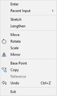
Figure 99: Grip Mode Contextual Menu
Stretch with grips
To stretch an object using grips, just click on the grip to be stretched, and after the grip turns red, move the grip to the new desired location.
Note: When working with objects such as circles and ellipses, the grips shown are for the object center point and the four quadrants. In this case, the distance is measured from the center of the object (or radial distance) and actions like stretch will actually change the object radius, and not the displacement from the selected grip.
Move with grips
- Select the grip to be used as a reference point.
- Right-click the mouse and chose Move.
- Move the selected objects to the desired location and click to place the objects.
- Press Enter, Spacebar, or Esc to cancel grip mode.
Rotate with grips
- Select the grip to be used as a reference point.
- Right-click the mouse and chose Rotate.
- If the rotation center point (base point) is not appropriate, right-click the mouse and choose Base Point to select a new base point.
- Move the mouse to rotate the selected objects and click to place the objects.
- Press Enter, Spacebar, or Esc to cancel grip mode.
Scale with grips
- Select the grip to be used as a reference point.
- Right-click the mouse and chose Scale.
- If the scale base point is not appropriate, right-click the mouse and choose Base Point to select a new base point.
- Enter the scale factor value and press Enter, or move the mouse to dynamically scale the selected objects and click to place the objects.
- Press Enter, Spacebar, or Esc to cancel grip mode.
Mirror with grips
- Select the grip to be used as a reference point.
- Right-click the mouse and chose Mirror.
- If the mirror base point is not appropriate, right-click the mouse and choose Base Point to select a new base point.
- Select a second point of the mirror line.
- Press Enter, Spacebar, or Esc to cancel grip mode.
Make multiple copies with grips
- Select the desired action from the contextual menu.
- Press C and press Enter, or Hold the Ctrl key while you perform the action. Continues making copies until you press Enter, Spacebar, or Esc.
Hands on editing objects
In this practice, you are going to exercise the many methods to edit objects. The drawing we are going to work is a landscape plan.
- Open AutoCAD, if not yet opened.
- Open the drawing Landscape Plan located in the Chapter 04 folder.
- Save the drawing as My Landscape Plan.
- Zoom to the pool area so that the whole pool fits the drawing area.
Let’s first create the pool steps using the Offset command
Command: O8
Specify offset distance or [Through/Erase/Layer] <1'-0">: 128
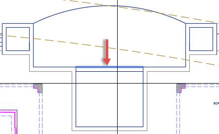
Select object to offset or [Exit/Undo] <Exit>: Select the line delimiting the shelf as shown in the following figure:
Specify point on side to offset or [Exit/Multiple/Undo] <Exit>: Click anywhere below the selected line.
Select object to offset or [Exit/Undo] <Exit>: Select the newly created line.
Specify point on side to offset or [Exit/Multiple/Undo] <Exit>: Click anywhere below the selected line.
Select object to offset or [Exit/Undo] <Exit>: Press Enter, Spacebar, or Escape (Esc) to complete the command.
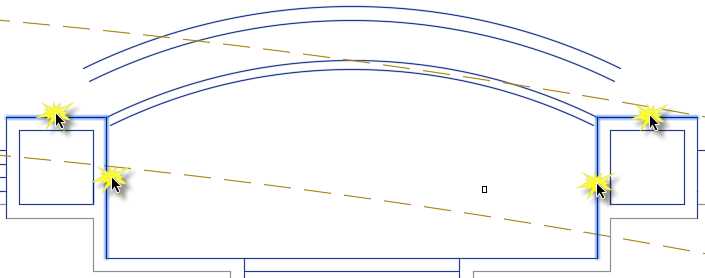
Next let’s create a vanishing edge and trough at arched edge of the pool.
Command: O8
Specify offset distance or [Through/Erase/Layer] <1'-0">: 88
Select object to offset or [Exit/Undo] <Exit>: Select the arc
Specify point on side to offset or [Exit/Multiple/Undo] <Exit>: Click anywhere below the arc
Select object to offset or [Exit/Undo] <Exit>: Press Enter, Spacebar, or Escape (Esc) to complete the command.
Command: Press Enter or the Spacebar to repeat the last command
Specify offset distance or [Through/Erase/Layer] <0'-8">: 2’6”8
Select object to offset or [Exit/Undo] <Exit>: Select the top arc
Specify point on side to offset or [Exit/Multiple/Undo] <Exit>: Click anywhere above the arc
Select object to offset or [Exit/Undo] <Exit>: Press Enter, Spacebar, or Escape (Esc) to complete the command.
Command: Press Enter or the Spacebar to repeat the last command
Specify offset distance or [Through/Erase/Layer] <3'-0">: 128
Select object to offset or [Exit/Undo] <Exit>: Select the newly created arc
Specify point on side to offset or [Exit/Multiple/Undo] <Exit>: Click anywhere above the arc
Select object to offset or [Exit/Undo] <Exit>: Press Enter, Spacebar, or Escape (Esc) to complete the command.
Notice that the new arcs created using the offset command do not touch the pool boundaries. To fix that, we are going to use the Extend command.
Command: EX8
Select objects or <select all>: Select the lines as shown in the following figure and then press Enter or the Spacebar to confirm the selection.
Select object to extend or shift-select to trim or [Fence/Crossing/Project/Edge/Undo]:
Path does not intersect with the bounding edge.
Select object to extend or shift-select to trim or [Fence/Crossing/Project/Edge/Undo]: Click near the end each end-point of the created arcs to extend
Select object to extend or shift-select to trim or [Fence/Crossing/Project/Edge/Undo]: Press Enter, Spacebar, or Esc to finish
Press Ctrl+S to save your drawing.
Now let’s build the stair steps to the right side of the pool deck. Zoom to the area so it fits the drawing areas as shown in the following figure:
Use the Offset command to offset both: the vertical line to the right, and the horizontal line to the top of the proposed stair. The offset distance is 12; repeat the offset three times for each line towards the building. The results should be like the following figure:
We need to fix and trim the lines. Zoom closer to the area to the trimmed (the top-right area where the step lines are crossing), then proceed as follows:
Command: TR8
Select cutting edges ...
Select objects or <select all>: Select the two step lines as shown in the following figure and then press Enter
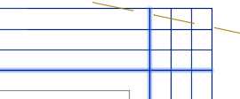
Select object to trim or shift-select to extend or [Fence/Crossing/Project/Edge/eRase/Undo]: Click the horizontal line to the right of the intersection
Select object to trim or shift-select to extend or [Fence/Crossing/Project/Edge/eRase/Undo]: Click the vertical line above the intersection
Select object to trim or shift-select to extend or[Fence/Crossing/Project/Edge/eRase/Undo]: Press Enter, Spacebar or Esc to finalize the command
Another approach to quickly trim segments in this type of scenario is using the command Trim as follows:
Command: F8
Select first object or [Undo/Polyline/Radius/Trim/Multiple]: R8 (set fillet radius)
Specify fillet radius <2'-3 11/16">: 08 (set radius as zero)
Select first object or [Undo/Polyline/Radius/Trim/Multiple]: M8 (multiple trim actions)
Select first object or [Undo/Polyline/Radius/Trim/Multiple]: Click on a line next to the intersection.
Select second object or shift-select to apply corner or [Radius]: Click the nearest intersecting line
Select first object or [Undo/Polyline/Radius/Trim/Multiple]: Click on a line next to the intersection.
Select second object or shift-select to apply corner or [Radius]: Click the nearest intersecting line
Select first object or [Undo/Polyline/Radius/Trim/Multiple]: Press Enter, Spacebar, or Esc to finalize the command
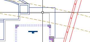
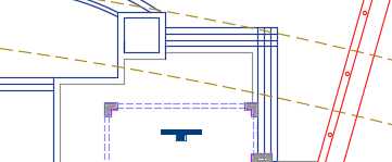
Zoom so that the whole pool deck fits within the drawing area. There is a table-set between the lanai and the lower-left corner of the pool shelf. We need a symmetric copy in the other side. We can accomplish this by using the Mirror command as follows:
Command: MI8
Select objects: Select the table set
Select objects: 8
Specify first point of mirror line: press and hold the Shift and Right-Click the mouse, select Mid from the Contextual Menu. _mid of Click the near the midpoint of a pool stair step
Specify second point of mirror line: press and hold the Shift and Right-Click the mouse, select Mid from the Contextual Menu. _mid of Click the near the midpoint of another pool stair step to create a vertical mirror line.
Erase source objects? [Yes/No] <No>: N8 (this will maintain the source, choosing Yes erases the source objects)
Press Ctrl+S to save your drawing, and let’s work in the front part of the site.
Command: Z8
Specify corner of window, enter a scale factor (nX or nXP), or [All/Center/Dynamic/Extents/Previous/Scale/Window/Object] <real time>: E8
We first need to change the paver pattern. To do so, we need to edit the hatch using the Hatch Editor contextual tab. Zoom closer to the front yard if needed.
- Select the Driveway hatch pattern. The Hatch Editor contextual tab is loaded in the ribbon.
- In the Pattern panel, find and select the pattern named AR-HBONE.
- In the Properties panel, change the scale to 1.
The driveway is now showing a Herringbone hatch pattern.
There is a vehicle (block) in the driveway, and we need to rotate it to fit the driveway natural flow. We can use the Move command or we can rotate in Grip mode. There is no rule for which method to use, but for this case, let’s rotate in Grip mode.
- Select the vehicle block. A blue, solid grip appears near the center of the car.
- Click the grip; it becomes red. Enter into Stretch mode (because this object is a block, stretch will act as move).
- Right-click the mouse and choose Rotate from the contextual menu.
- If you know the rotation angle, you could enter the value here. In this case the rotation angle is unknown, so we will select the direction. Press and hold the Shift key, right-click the mouse, and choose Center from the contextual menu.
- Click anywhere on one of the arc segments, creating the arched drive.
- Press Esc to cancel the section.
Next we will create two shrub beds around the driveway. There are two polylines that will define the path to distribute the objects representing the shrubs. The path to the right has the object located at the left end of the path. Before creating the array, copy the shrub to one of the end points of the path to the left.
- Select the shrub (the small green circle with a cross in the center).
- Click the grip in the center of the block.
- Right-click and choose Move.
- Right-click and choose Copy.
- Press and hold Shift, right-click the mouse, and choose Endpoint to override snap to endpoint of segment.
- Click near the endpoint of the arc to the left.
- Press Esc to finalize Grip mode.
- Press Esc to clear the selection.
- Press Ctrl+S to save your drawing.
Next we are going to create an array that follows the paths around the driveway. Click on the Path Array tool to start a path array.
Select objects: Select the shrub block at the end of the polyline path to the right.
Select objects: Press Enter to commit the selection.
Select path curve: Select the polyline to the right for the array path.
Select grip to edit array or [ASsociative/Method/Base point/Tangent direction/Items/Rows/Levels/Align items/Z direction/eXit]<eXit>: From the Array Creation contextual tab, Items panel, enter 36 in the Between field and press Enter.
Select grip to edit array or [ASsociative/Method/Base point/Tangent direction/Items/Rows/Levels/Align items/Z direction/eXit]<eXit>: Press Enter, Spacebar, or Esc to finish the command.
Repeat the previous steps to create the shrub bed in the left side of the driveway.
Select both polylines that were used to define the array path. You may need to zoom closer to make sure to not select the array.
Press the Delete key to erase the paths.
Zoom closer to the palm tree at the center of the driveway. There is a block representing a shrub, and it needs to be arrayed around the palm tree. We are going to use the Array Polar command to accomplish this:
From the Home tab, Modify Panel, click on the Polar Array tool:
Command: _arraypolar
Select objects: Select the shrub symbol under the palm tree symbol.
Select objects: Press Enter to confirm selection and move to the next step.
Specify center point of array or [Base point/Axis of rotation]: Press and hold the Shift Key, right-click the mouse, and select Insert from the contextual menu: _ins of Hover over the palm tree, an amber symbol shows at the center of the symbol. Left-click the mouse to select the Palm Tree Insertion point as center of the array.
Select grip to edit array or [ASsociative/Base point/Items/Angle between/Fill angle/ROWs/Levels/ROTate items/eXit]<eXit>: On the Array Creation contextual tab, enter 12 for the Items count and press Enter.
Select grip to edit array or [ASsociative/Base point/Items/Angle between/Fill angle/ROWs/Levels/ROTate items/eXit]<eXit>: Press Enter or Esc to finalize the command.
Now we need to create a shrub bed in the courtyard. There is a shrub symbol next to the lower-left corner of the courtyard walls. We are going to create a rectangular array using that block.
Click on the Rectangular Array tool and follow these steps:
Command: _arrayrect
Select objects: Select the shrub symbol.
Select objects: Press Enter to confirm selection and move to the next step.
Select grip to edit array or [ASsociative/Base point/COUnt/Spacing/COLumns/Rows/Levels/eXit]<eXit>: On the Array Creation contextual tab, Columns Panel, enter 3 for the Columns count field and 48 for the Between value (this is space between items, base-point to base-point).
Select grip to edit array or [ASsociative/Base point/COUnt/Spacing/COLumns/Rows/Levels/eXit]<eXit>: Rows Panel, enter 8 for the Rows count field and 48 for the Between value.
Select grip to edit array or [ASsociative/Base point/COUnt/Spacing/COLumns/Rows/Levels/eXit]<eXit>: Press Enter or Esc to finalize the command.
Next we should amend the walk area between the pergola and the driveway. Zoom to the sidewalk. We need to chamfer the corners of the sidewalk apron to create a smoother transition. This will be accomplished using the Chamfer command:
Command: CHA8
Select first line or [Undo/Polyline/Distance/Angle/Trim/mEthod/Multiple]: D8
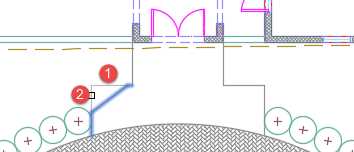
Specify first chamfer distance <0'-0">: 488 This is the chamfer distance for the line number 1 shown in the previous figure.
Specify second chamfer distance <4'-0">: 368 This is the chamfer distance for the line number 2 shown in the previous figure.
Select first line or [Undo/Polyline/Distance/Angle/Trim/mEthod/Multiple]: Left-click the line number 1 shown in the previous figure.
Select second line or shift-select to apply corner or [Distance/Angle/Method]: Left-click the line number 2 shown in the previous figure.
Repeat the previous action to camper the right side of the sidewalk apron as well.
To complete this exercise, we need to move the green circle, located to the right of driveway access, closer to the driveway apron, as shown in the following figure, and then add trees to additional locations. Please follow these steps:
Command: M8
Select objects: Select the tree symbol.
Select objects: Press Enter to commit selection.
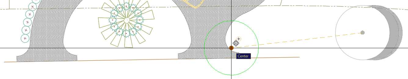
Specify base point or [Displacement] <Displacement>: Press and hold the Shift key and right-click the mouse. From the contextual menu, select Center.
Specify base point or [Displacement] <Displacement>: _cen of Click on the tree symbol circumference.
Specify second point or <use first point as displacement>: Press and hold the Shift key and right-click the mouse. From the contextual menu, select Center _cen of – Left-click on the arc as shown on the previous figure.
Now proceed with the copies:
Command: CO
Select objects: Select the Tree symbol you relocated in the previous action. Press Enter to commit the selection.
Specify base point or [Displacement/mOde] <Displacement>: Press and hold the Shift key and Right-click the mouse. From the contextual menu, select Center _cen of Click on the tree symbol circumference.
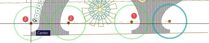
Specify second point or [Array] <use first point as displacement>: Copy the Tree symbol to locations as shown in the following figure. Make sure to use Center Object Snap override. Press Enter, Spacebar, or Esc to finish the command.
Press Ctrl+S to save your drawing.
Close the drawing and then open the drawing named ColumnBase Partial located in the Chapter 04 folder. This is the same column base we worked on Chapter 3, and the objective of the following exercise is to convert the arcs and lines to a single polyline. We will also practice changing the height of the column base using the Stretch command.
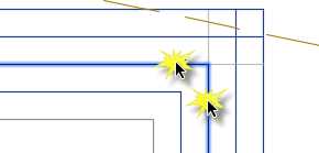
- From the Home tab, Modify panel, click on the Stretch tool.
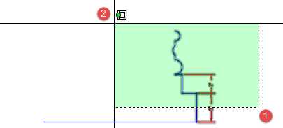
- Click a point to the right of the objects to be stretched (point 1 shown in the previous picture), and then a point to the left of the elements to be stretched (point 2.) It is critical that all points that will participate of the Stretch action are enclosed by the Crossing Window, and that elements to be affected to be crossed are enclosed by the Crossing Window.
- Press Enter to commit the selection.
- Click anywhere in the drawing area to mark the base point.
- Make sure that Polar Tracking is on, and that the angle increment includes 90º (see the “Other input methods” section in Chapter 2).
- Move the cursor up in the drawing area. The objects start to stretch following the cursor direction. Make sure that the Polar Tracking is showing 90º, type 1, and press Enter.
- The base is stretched and the dimension was updated to 4”.
Next we need to join the elements to create a polyline:
Command: PE8
Select polyline or [Multiple]: Select the vertical blue line (measuring 4”) and press Enter.
Because the selected object is a line (not a polyline), AutoCAD confirms if it should be converted to a polyline. We need to accept by entering Y in the prompt:
Object selected is not a polyline Do you want to turn it into one? <Y> Y8
Next we will join the other segments that define the base profile:
Enter an option [Close/Join/Width/Edit vertex/Fit/Spline/Decurve/Ltype gen/Reverse/Undo]: J8
Select objects: Create a Crossing Window as seen in the previous figure in the stretch action. 11 found
Select objects: Press Enter to join the selected segments to the polyline.
8 segments added to polyline
Enter an option [Close/Join/Width/Edit vertex/Fit/Spline/Decurve/Ltype gen/Reverse/Undo]: Press Enter, Spacebar, or Esc to finish the command.
Note: Dimension lines are automatically filtered from the selection since they cannot be joined or converted to polyline.
Position the mouse over the new polyline to confirm if objects were joined.
Let’s use the Mirror command to mirror-copy the polyline to define the profile to the left:
Command: MI8
Select objects: Select the polyline. 1 found
Select objects: Specify first point of mirror line: Press and hold the Shift key and right-click the mouse. From the contextual menu, select Midpoint. _mid of
Specify second point of mirror line: Make sure that Polar Tracking is on, move the cursor 90o up or down, and left-click to define the mirror line.
Erase source objects? [Yes/No] <No>: N8 (we need to keep the source object.)
Let’s join them all to create a single polyline:
Command: PE8
By default, you can edit one polyline only. We are going to use the Multiple option to select all objects in a single run:
Select polyline or [Multiple]: M8
Now let’s select all objects in the drawing. Dimension objects are automatically excluded from joining:
Select objects: ALL8
5 found
Select objects: Press Enter to commit selection.
Convert Lines, Arcs and Splines to polylines [Yes/No]? <Y> Y8
Enter an option [Close/Open/Join/Width/Fit/Spline/Decurve/Ltype gen/Reverse/Undo]: J8
Enter fuzz distance or [Jointype] <0'-0">: 08
10 segments added to polyline
To close the polyline:
Enter an option [Close/Open/Join/Width/Fit/Spline/Decurve/Ltype gen/Reverse/Undo]: C8
Enter an option [Close/Open/Join/Width/Fit/Spline/Decurve/Ltype gen/Reverse/Undo]: Press Enter, Spacebar, or Esc to finish the command.
Now the column base is a single polyline object. Press Ctrl+Shift+S to open the Save Drawing As dialog box. Save your drawing as MyColumnBasePL.dwg.
Chapter summary
In this chapter, you learned how to select, modify, modify, and create copies of objects. AutoCAD’s editing power goes way beyond what was covered here, and you surely will find your own ways to work with the many modification tools AutoCAD provides.
In the next chapter you will learn how to reuse objects in very effective way. See you there.
- 1800+ high-performance UI components.
- Includes popular controls such as Grid, Chart, Scheduler, and more.
- 24x5 unlimited support by developers.