
AutoCAD Succinctly®

CHAPTER 3
Let There Be Lines
It’s time to start creating your world. In this chapter, you’ll learn how to create the most common AutoCAD geometries
Open AutoCAD, if is not yet opened, and start a new drawing based on the ACAD Succinctly template.
Object snaps
Before we start creating geometries, let us talk a little about object snaps. Object naps are drawing helpers that allow you to select precise locations when prompted for a point.
AutoCAD has a feature called AutoSnap (Figure 39), which automatically snaps to the nearest point in an existing object. A visual confirmation marker is displayed with a tooltip when approaching an existing object when Object Snap is on. Press the F3 key to toggle AutoSnap on or off.
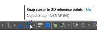
Figure 39: Object Snap toggle button
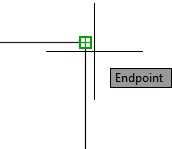
Figure 40: Snapping to the end point of a line
To see or set running object snaps, click in the small triangle to the right of the button to show the current selection. To turn the Object Snap mode on or off, click on the desired mode. A checkmark is displayed to the left of the active modes, as shown in Figure 41.
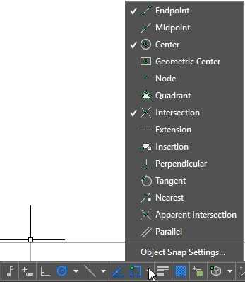
Figure 41: Running Object Snaps
To temporary override running Object Snap modes, press and hold the Shift key and right-click the mouse button to show the Object Snap Override menu (see Figure 42) and select the temporary object snap mode of your choice. Temporary object snaps are active only for the current point to selection.

Figure 42: Override running object snaps
AutoCAD Geometries
Line
Command: LINE
Alias: L
The line is the most basic and common AutoCAD object. Lines are straight segments connecting two given points (start and end points.) To draw a line, click the Line tool. To start a line, click the Line tool in the home Tab, or type LINE (or just L) in the command window and press Enter or the Spacebar.

Figure 43: Line Command in Home Tab
When you run the LINE command, you can create a series of connected line segments. Each segment is an independent object that can be modified or erased without affecting the other segments.
It’s time to produce something. Let’s create the following drawing:
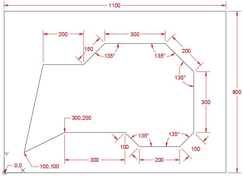
The following steps guide you on creating the external rectangle. You can run the LINE command from either the command window or the ribbon tool.
Command: L8
Specify first point: 0,08
Specify next point or [Undo]: @1100,08
Specify next point or [Undo]: @0,8008
Specify next point or [Close/Undo]: @-1100,08
Specify next point or [Close/Undo]: C8
As you start creating the drawing, it may extend beyond the current screen boundary. Double-click the middle button of the mouse to zoom to the drawing extension, or type Z and press Enter, then type E and press Enter.
In the previous steps, we started the first line segment right at the origin of the UCS by entering the absolute coordinates (0,0), followed by three relative coordinates, and finally closing the rectangle by typing C.
Tip: If you create a line segment with incorrect coordinates, just press U and then press Enter to undo the line segment without command interruption. You may undo as many segments as you like, but the only way to redo a segment is by reentering the point coordinates.
To create the remaining lines of the drawing, execute the command sequence as follows:
Command: L8
Specify first point: 100,1008
Specify next point or [Undo]: 300,2008
Specify next point or [Undo]: @300,08
Specify next point or [Close/Undo]: @100<-458
Specify next point or [Close/Undo]: @200<08
Specify next point or [Close/Undo]: @100<458
Specify next point or [Close/Undo]: @300<908
Specify next point or [Close/Undo]: @200<1358
Specify next point or [Close/Undo]: @300<1808
Specify next point or [Close/Undo]: @150<2258
Specify next point or [Close/Undo]: @200<1808
Specify next point or [Close/Undo]: C8
Note that I have used a mix of absolute, relative, and relative polar coordinates. There is no restriction on which coordinate input method you choose. For example, entering @-300,0 would create the same segment as @300<180 creates.
Because angles are measured counter-clockwise from the positive direction of the X axis by default, I had to calculate a simpler angle measurement to enter. For example, in the third line segment, if you entered 135 for the angle measurement, it would result in a line segment to the top right from the previous point. Since we needed to go down and right, we entered -45 (90-135) for the angle measurement.
Save your drawing as Lines01.dwg.
Note: AutoCAD 2016 saves as AutoCAD 2013 file format by default, meaning that you can open files edited on AutoCAD 2016 on any AutoCAD version since AutoCAD 2013. If you need to open the drawing on older AutoCAD versions, select the version from the Files of type drop-down list.
Tip: To quick-save the drawing, you can use the shortcut Ctrl+S keys combined. To save the drawing with a different name, use Ctrl+Shift+S to show the Save Drawing As dialog.
Start a new blank drawing. We are going to create the following drawing by using Polar Tracking and distance input:
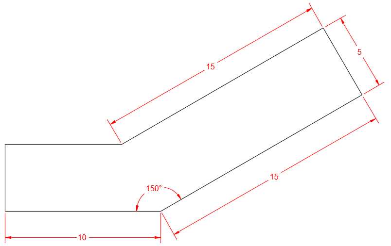
Figure 45: Lines02.dwg
Make sure that Object Snap, Object Snap Tracking, and Polar Tracking are on, and that Polar Tracking is set to the 15º increment, as explained in Chapter 2.
Your status bar should look similar to the following figure, where a blue icon means that the corresponding helper is on:
![]()
Tip: Press F3 to toggle Object Snap, F10 to toggle Polar Tracking, and F11 to toggle Object Snaps Tracking.
Start the line command, either by typing in the command window, or clicking on the ribbon tool.
Command: L8
Specify first point: Click anywhere in the drawing area
For the next points we will be positioning the mouse so that it simulates the direction of the vector, as shown in the Figure 46. Enter only the segment length in the command prompt and press Enter.
![]()
Figure 46: Polar Tracking at 0º
Specify next point or [Undo]: 108
![]()
Figure 47: Polar Tracking at 30º
Specify next point or [Undo]: 158
![]()
Figure 48: Polar Tracking at 120º
Specify next point or [Close/Undo]: 58
![]()
Figure 49: Polar Tracking at 210º
Specify next point or [Close/Undo]: 158
Next we are using a combination of polar tracking and object snap tracking. First hover over the left-end point of the first segment created as shown on Figure 50. This will activate object snap on the point. When you move the mouse up approximately at 90º, the object snap tracking line is displayed. Continue moving the cursor up until the intersection with the Polar Tracking appears, as shown on Figure 51, and then left-click to select the point.
![]()
Figure 50: Activate Object Snap Tracking for a point
![]()
Figure 51: Object Snap Tracking and Polar Snap Tracking intersection
Specify next point or [Close/Undo]: Press the mouse left-button at the intersection between the Object Snap Tracking line and the Polar Tracking line.
Specify next point or [Close/Undo]: C8
Save your drawing as Line02.dwg.
Line Command Prompts
- Specify first point: Selects the first point of the line segment. Pressing Enter will continue from the last point of the previously created object. If the previous object is an arc, pressing Enter will continue the line from the arc last point and tangent to the arc.
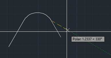
Figure 52: Continuing a line from a previously created arc
- Specify next point: Selects the endpoint of the line segment (and the start point of next segment until the command is completed).
- Undo: Undoes the last line segment of the series.
- Close: Creates a line segment, starting at the end point of the last segment and ending at the first point of the first line segment in the series, and finishes the command. You need to have at least two line segments in the series in order to use the Close command.
Tip: You can just click the option in the command window or type the corresponding uppercase blue letter.
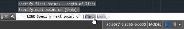
Figure 53: Select command option from Command Window
Circle
Command: CIRCLE
Alias: C or CI
Use the Circle command to create a circle object in AutoCAD. The default method of creating a circle is by selecting the circle center point and entering the radius value. Other methods to create circles are available if you click the small triangle below the Circle tool in the Draw Tab on the Home Panel.
To start creating a circle, click the Circle tool in the Draw tab, or enter CIRCLE (or simply C) and press Enter or the Spacebar.
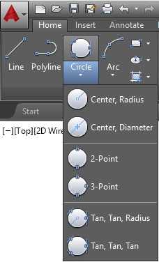
Figure 54: Circle Command in the Home tab
![]()
Figure 55; Circle command prompt options
Note that the command window shows the options to create the circle. To select an option, click on the option or type the Alias, shown in blue, and press Enter or the Spacebar. You can also right-click and select the option from the context menu that pops up. This practice is similar on all AutoCAD commands.
You can create a circle using any of the following options:
Center, Radius: This is the default option to create a circle when typing the command at the command window and at the ribbon until selecting another option. To create a circle, run the command, and select a point by entering the coordinate values or choosing them on screen. Enter the radius length by typing it at the command window or selecting a point. When you select a point, the start point of the radius is the last point selected, which is the center of the circle.
Center, Diameter (D): Same as Center, Radius, but you will be entering the diameter length instead. When running the command from the command window, you can enter D and press Enter or the Spacebar before entering the length. This will instruct AutoCAD that the next length is the circle diameter.
Points (2P): To create the circle by selecting two points. The distance between the two points is the circle diameter.
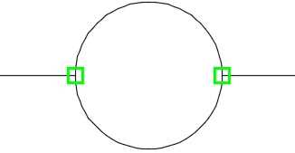
Figure 56: 2 Points circle
Points (3P). This will create a circle in which the circumference passes through three selected points.
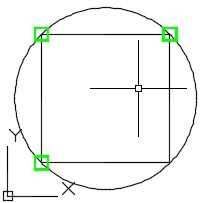
Figure 57: 3 Points circle
Tan, Tan, Radius (TTR). This creates a circle by selecting two tangent points and the circle radius. Sometimes the selection may result in more than one possibility to create the circle. When this happens, AutoCAD creates the circle in which the tangent points are nearest to the points you picked.
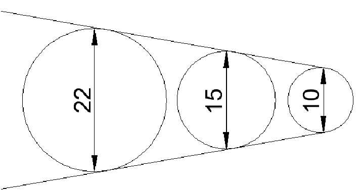
Figure 58: Circle tangents to the same two lines with different radii
Tan, Tan, Tan. This creates a circle that is tangent to three selected points. This option is not available as a command window option, but, actually, this is the 3P option used in combination with the tangent object snap, which you will learn about later in the book.
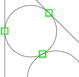
Figure 59: Circle with three tangent points
Arc
Command: ARC
Alias: A
Arcs are created counterclockwise by default. Changing the angle direction using the Unit command discussed on Chapter 1 also affects the direction in which arcs are constructed.
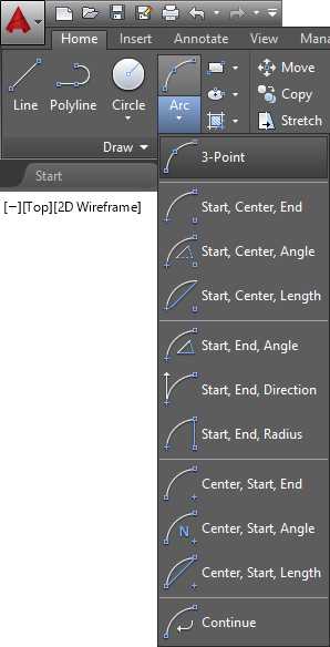
To create an arc, click the Arc tool in the ribbon’s Home tab (Figure 62) or enter A (alias of the ARC command) in the command window and press Enter or the Spacebar. When running Arc from the command window, the prompt changes to match the next point selection possibilities.

Figure 60: Arc command in the Command Window
3 Point. The default method to create an arc is by selecting three points in the drawing area. The arc is created passing through the three selected points.
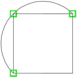
Figure 61: Arc created with three points
Note: All construction methods in the ribbon tool are available through the command window with the combination of your choice on the run. Using the command window will make you more productive on most AutoCAD commands.
Tip: Some arc creation methods allow the user to change the direction of the arc by holding the Ctrl key when selecting the last point.
Start, Center, End. In this method, the first point selected is the start point of the arc, the second point selected is the center point, and the third (and last) point is the end point of the arc.

Figure 63: Start, Center, End arc
Start, Center, Angle: In this construction method, you first select the arc start point and then the center point of the arc defining the arc radius. The last prompt specifies the included angle for the arc. You may enter the angle measurement or select a point to define the angle.

Start, Center, Length: Create an arc by selecting the start point, center, and the length of the chord.

Start, End, Direction: Create an arc by selecting the start point, end point, and the tangent direction for the arc.

Start, End, Radius: Create an arc by selecting the first point, end point, and the radius.

Contiguous Tangent Arcs and Lines: You can continue an arc from a previously created arc or line. The start point of the arc will be the last point of the previously created object.
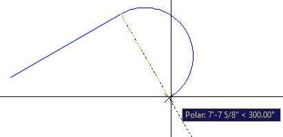
Figure 64: Creating an arc by continuing from a previously created line
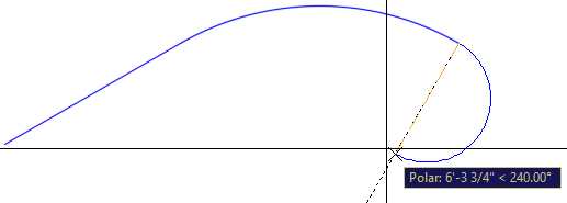
Figure 65: Continuing an Arc from a previously created arc
Okay, let’s produce something. We are going to draw a column base, as shown in the following figure:

Make sure that Object Snap, Object Snap Tracking, and Polar Tracking are on and Polar Tracking is set to the 15º increment, as explained in Chapter 2.
Change Drawing Units to Architectural (see Drawing Units in Chapter 1).
Create a layer called ColumnBase with the color 5 (blue), and make it the current layer. See “Creating Layers” in Chapter 2 for a review on creating layers.
Command: L8
Specify first point: 0,08
Move the mouse up so that the tracking tip shows the angle as 90º.
Specify next point or [Undo]: 38
Move the mouse to the left so that the tracking tip shows the angle as 180º.
Specify next point or [Undo]: 1.58
Move the mouse up so that the tracking tip shows the angle as 90º.
Specify next point or [Close/Undo]: 28
Move the mouse to the left so that the tracking tip shows the angle as 180º.
Specify next point or [Close/Undo]: .758
Specify next point or [Close/Undo]: 8
Command: A8
Specify start point of arc or [Center]: Click next to the end point of the last line created, make sure that the OSNAP tip is displayed as Endpoint, as shown in the following figure.

Specify second point of arc or [Center/End]: C8
Specify center point of arc: @0,.758
Specify end point of arc (hold Ctrl to switch direction) or [Angle/chord Length]:8
Command: L8
Specify first point: Click near the end point of the previously created arc

Move the mouse up so that the tracking tip shows the angle as 90º.
Specify next point or [Undo]: .5
Specify next point or [Undo]: 8
Command: A
Specify start point of arc or [Center]: @0,1
Specify second point of arc or [Center/End]: E
Specify end point of arc: Click near the end point of the previously created line
Specify center point of arc (hold Ctrl to switch direction) or [Angle/Direction/Radius]: R8
Specify radius of arc (hold Ctrl to switch direction): .758
Command: L8
Specify first point:
Specify next point or [Undo]: .58
Specify next point or [Undo]:
Command: A8
Specify start point of arc or [Center]:
Specify second point of arc or [Center/End]: E8
Specify end point of arc: @0,18
Specify center point of arc (hold Ctrl to switch direction) or [Angle/Direction/Radius]: D8
Specify tangent direction for the start point of arc (hold Ctrl to switch direction):

Command: L8
Specify first point: 0,08
Move the mouse to the left so that the tracking tip shows the angle as 180º.
Specify next point or [Undo]: 1'4"8
Specify next point or [Undo]: 8
Now let’s mirror copy the profile to create the left side of the column base. You will learn more about the Mirror command in the next chapter.
Command: MI8
Select objects: Click a point to the left and above the drawing to be selected and then click a point to the right and below the arc, as shown in the following figure:

Select objects: 8
Specify first point of mirror line: MID8 (or hold shift and right-click to display the Override Running Object Snap menu and select Midpoint)
Of Click near the midpoint of the wide horizontal line
Specify second point of mirror line: Select a point above or below making sure that polar tracking is at 90O
Erase source objects? [Yes/No] <No>: N8
Zoom to drawing extension. After running the command, your drawing will fill your drawing area.
Command: Z8
Specify corner of window, enter a scale factor (nX or nXP), or [All/Center/Dynamic/Extents/Previous/Scale/Window/Object] <real time>: E8
Now we will zoom out just a little (10%) to make the drawing more readable:
Command: Z8
Specify corner of window, enter a scale factor (nX or nXP), or [All/Center/Dynamic/Extents/Previous/Scale/Window/Object] <real time>: .9x8
Create a layer called ColumnBase-vis with the color 8, and make it the current layer.
Create lines connecting the end points of each level of the column base.
Save your drawing as ColumnBase.dwg.
Polyline
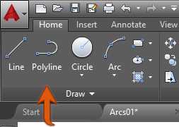
Figure 66: Polyline Tool
A polyline is a single object composed of multiple line segments or arcs. To create a polyline composed only of straight segments is similar to creating standard lines.
Command: PL or PLINE
Polyline displays the following prompts:
Specify start point: Sets the polyline start point. A small tick marks the polyline first point until the command is completed (see Figure 67). Pressing Enter with an empty prompt starts a new polyline from the last point selected when creating a line, arc, or other polyline.
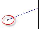
Figure 67: Polyline first point tick mark
Linear Segments Prompt
Specify next point or [Arc/Close/Halfwidth/Length/Undo/Width]:
- Arc: Start creating a curved polyline tangent to the previous segment.
- Length: Create a contiguous straight segment with a specified distance. If the previous segment is an arc, the new line segment is tangent to the arc.
Arched Segments Prompt
Note: Arched polyline segment construction methods are similar to generic Arc construction methods.
Specify endpoint of arc (hold Ctrl to switch direction) or
[Angle/CEnter/CLose/Direction/Halfwidth/Line/Radius/Second pt/Undo/Width]:
- Endpoint of arc: Completes an arc segment. The arc segment is tangent to the previous segment of the polyline.
- Angle: Specifies the included angle of the arc from the start point.
- Direction: Specifies the tangent for the arc segment.
- Line: Sets the polyline construction mode back to straight segments.
- Radius: Specifies the radius of the arc segment.
- Second pt: Specifies the second point and endpoint of a three-point arc.
Common Prompt Options
- Close: Connects the first and last segments to create a closed polyline. Be aware that the alias for linear segments is C, while the alias for arched segments is CL to avoid conflicts with Center (CE).
- Halfwidth: Specifies the width from the center of a wide segment to an edge. This value remains until changed again and persists for new polylines for the current drawing.
- Width: Specifies the full width of the next segment. This value remains until changed again and persists for new polylines for the current drawing.
- Undo: Removes the last segment added.
Note: Polylines with a defined width plot as defined and are affected by plotting scale as well as modifications made by scale commands. To reset, set the width to 0.
Rectangle
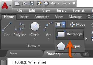
Figure 68: Rectangle Tool in the ribbon
Command: RECTANGLE
Alias: REC or RECTANG
Creates a rectangle according to parameters passed in the command window prompt:
Specify first corner point or [Chamfer/Elevation/Fillet/Thickness/Width]:
Specify other corner point or [Area/Dimensions/Rotation]:
You can quickly create a rectangle by selecting two points in the drawing area (First corner and Other corner.)
For example, the rectangle created in Figure 44 could be created as follows:
Command: REC8
Specify first corner point or [Chamfer/Elevation/Fillet/Thickness/Width]: 0,08
Specify other corner point or [Area/Dimensions/Rotation]: @1100,8008
Note: For the “Other corner point” input, you may simply enter 1100,800 since the first point is at the UCS origin, and the relative and absolute coordinates are the same in this case.
Or by simply entering the rectangle dimensions as follows:
Command: REC8
Specify first corner point or [Chamfer/Elevation/Fillet/Thickness/Width]: 0,08
Specify other corner point or [Area/Dimensions/Rotation]: D8
Specify length for rectangles <10.0000>: 11008
Specify width for rectangles <10.0000>: 8008
Specify other corner point or [Area/Dimensions/Rotation]: Select a point to the top right of the first point
Rectangle options:
- Chamfer: Allows the user to specify chamfered corners for the rectangle with determined chamfer lengths. The chamfer lengths persist for new rectangles until changed.
- Elevation: Specifies the Z level for the rectangle. New rectangles are created at the defined Z level until changed.
- Fillet: Sets a radius to create rectangles with rounded corners.
- Thickness: Defines the segment thickness (height) for new rectangles.
- Width: Specifies the line width for new rectangles.
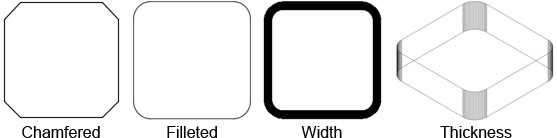
Figure 69: Rectangle Methods
Polygon
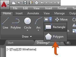
Figure 70: Polygon Tool in the Ribbon
Command: POLYGON
Alias: POL
The Polygon method creates a closed polyline with a defined number of equal sides. The minimum number of sides is three, and the maximum is 1,024. The following figures show two methods of creating polygons.

To understand the construction of polygons, let’s first create two circles, as listed in the following steps:
Command: C8
Specify center point for circle or [3P/2P/Ttr (tan tan radius)]: 3,38
Specify radius of circle or [Diameter]: 2.58
Command: C8
Specify center point for circle or [3P/2P/Ttr (tan tan radius)]: 10,38
Specify radius of circle or [Diameter] <2.5000>: 2.58
Now let’s fit the drawing to screen:
Command: Z8
Specify corner of window, enter a scale factor (nX or nXP), or [All/Center/Dynamic/Extents/Previous/Scale/Window/Object] <real time>: E8
Command: Z
Specify corner of window, enter a scale factor (nX or nXP), or [All/Center/Dynamic/Extents/Previous/Scale/Window/Object] <real time>: .7X8
Now let’s create the two hexagons (6-sided polygons). The first will be circumscribed about the circle to the left, and the second inscribed in the circle to the right.
Follow the steps to create the first hexagon:
Command: POL8
POLYGON Enter number of sides <4>: 68
Specify center of polygon or [Edge]: CEN8
Of place the cursor next the perimeter of the circle to the left. A OSNAP tip reads “Center” and a small amber circle appears at the center of the circle. Left-click to select the center point of the circle.

Enter an option [Inscribed in circle/Circumscribed about circle] <I>: C8
Specify radius of circle: 2.58
Now the second hexagon:
Command: POL8
POLYGON Enter number of sides <6>: 68
Specify center of polygon or [Edge]: CEN8
Of place the cursor next the perimeter of the circle to the right. A OSNAP tip reads “Center” and a small amber circle appears at the center of the circle. Left-click to select the center point of the circle.
Enter an option [Inscribed in circle/Circumscribed about circle] <C>: I8
Specify radius of circle: 2.58
Fit the drawing to screen, if needed, using the Zoom command.
Save your drawing as Polygons.dwg.
Other creation methods:
Edge: Creates a polygon by specifying the endpoints of the first edge.

Hatch
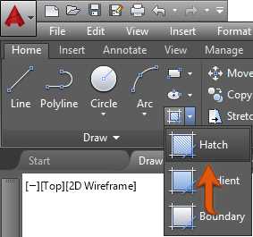
Figure 71: Hatch Tool in the Ribbon
Command: HATCH
Alias: H
The hatch command allows the user to fill closed areas with predefined and custom patterns, as well as solid and gradient fills.
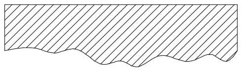
Figure 72: Hatch filled area
When you run the Hatch command or select a hatch object, the Hatch contextual tab is loaded and activated showing the hatch options.
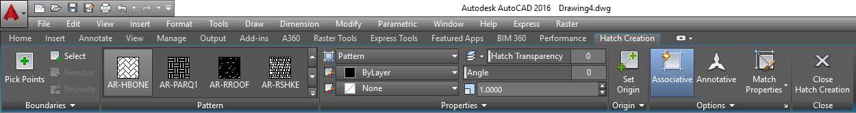
Figure 73: Hatch Contextual Tab
The Hatch contextual tab includes the following panels and tools:
- Boundaries panel: Includes tools for addition and removal of areas to be hatched

- Pick Points: Allows the user to select boundaries by clicking inside of closed areas
- Select: Allows the user to select objects to be hatched
- Remove: Removes a boundary area from the selection set
- Recreate: Available only when editing the hatch; creates a closed polyline of the hatch boundary
- Pattern Panel: List of available hatch patterns in AutoCAD
- Properties Panel: Allows the user to set and modify properties for the hatch

- Hatch Type: Allows the user to select the type of fill to be applied. You can choose from Pattern (default), Solid, Gradient, and User defined.
- Color: Sets the hatch color. If Hatch Type is set to Gradient, this becomes the gradient fill start color (Color 1).
- Background Color: Sets a color for the hatch background. If Hatch Type is set to Gradient, this becomes the gradient fill end color (Color 2).
- Hatch Transparency: Sets the hatch of fills transparency level from 0 to 90% where 0 is totally opaque hatch.
- Angle: Changes the hatch pattern angle. The angle is relative to the X axis for the current UCS.
- Scale: Allows increasing or decreasing pattern visibility scale. This option is available only when Hatch Type is set as Pattern.
- Layer Name: Allows the user to set the hatch layer to which the hatch is assigned.
- Relative to Paper Space: Scales the pattern relative to paper space units allowing the have consistent scale display (available only when working on layouts).
- Double: Used for User Defined Hatch Type; creates another set of lines perpendicular to the original lines.
- Origin Panel: Controls the base point to generate pattern. This is very useful when creating patterns, such as tiles, where you need to have control of the pattern start point.
- Options panel: Includes a set of tools to manage pattern fill mode.
- Associative: Maintains the pattern associated with the original boundary objects. If the boundary is modified, the hatch pattern is updated to match the changes.
- Annotative: Makes the pattern scale relative to annotative scale sets. (You will learn about Annotative Objects in Chapter 6.)
- Match Properties: Copies hatch properties from an existing hatch object.
Let’s see how the Hatch command works by creating adding hatches to the site plan drawing.
If you have not yet done so, please download the drawings for this book from DRAWING_LOCATION.
Open the SitePlan.dwg file located in the Chapter03 folder.

Let’s start by adding hatch to the building footprint. Zoom closer to the building area using your preferred zoom tool. The building footprint is a dark blue polyline, as shown in the previous figure. Proceed with the following steps:
Activate the layer L-Deck Pavers by selecting it from the Layer list in the Home tab Layers Panel.
Note: Make sure that no object is selected before selecting a layer. Selecting a layer while one or more objects are selected will assign the selected objects to the layer. Press the Escape (Esc) key to cancel any selection before picking a layer.
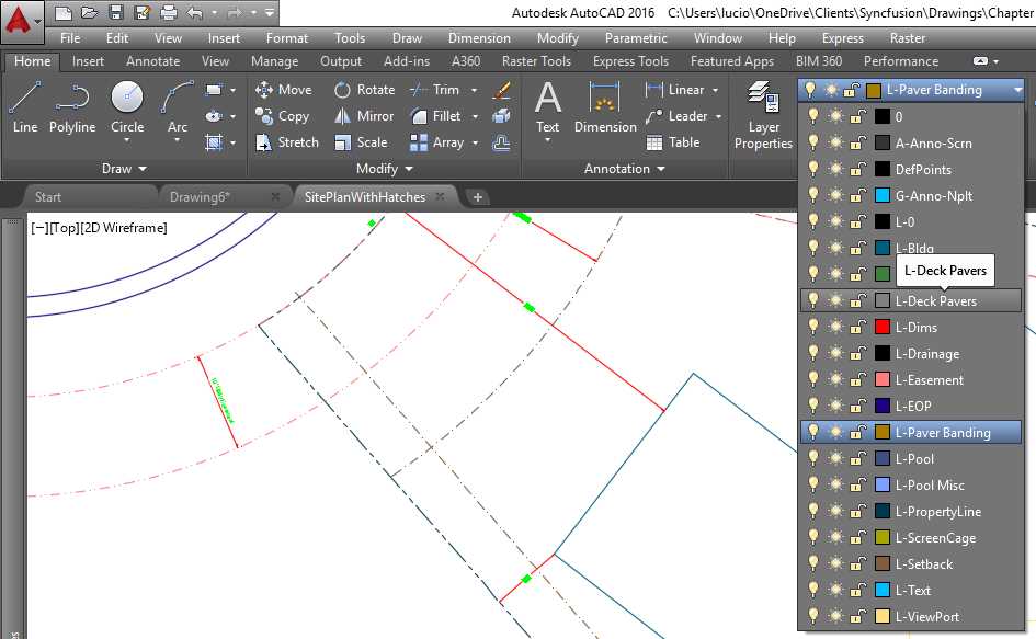
Figure 74: Making a Layer Active
Move the UCS and place it on the top-left corner of the building.
- Click on the UCS icon at the bottom-left corner of the drawing area. A blue box depicting the origin and two blue circles at the end of each axis are displayed.
- Click the blue box and drag it to the top-left corner of the building. Make sure you see and amber rectangle depicting the End Point of the line, and click the mouse again.
- Click on the blue circle depicting the X axis to rotate the UCS, and then select a point south of the same line where the origin was set. The UCS icon should show, as seen in the next figure. Press the Escape key to cancel the selection. Note that your cursor has changed to match the UCS orientation. Anything you create now will be referent to this UCS.

Run the hatch command by clicking the hatch tool or entering H, and press Enter in the command window.
Command: H8
The Hatch (Hatch Creaion) contextual tab shows in the ribbon. In the Boundaries panel, click the Select tool.
Select objects or [picK internal point/Undo/seTtings]:_S
Click on the building footprint boundary to add it to the selection set.
Select objects or [picK internal point/Undo/seTtings]:1 found
The hatch appears on the selected boundary as a solid gray fill. Make sure that ANSI31 is selected in the Pattern panel, and then, in the Properties panel, set the scale to 96 and press Enter.

Select objects or [picK internal point/Undo/seTtings]: Press the Escape (Esc) key to complete the command.
Once again move the UCS to the deck area, as shown in the following figure:

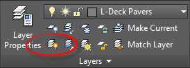
From the Home tab, Layers panel, click on Turn Layer Off tool (see the following figure.)

Command: LAYOFF
Current settings: Viewports=Vpfreeze, Block nesting level=Block
Select an object on the layer to be turned off or [Settings/Undo]: Click on a Text object.
Layer "L-Text" has been turned off.
Select an object on the layer to be turned off or [Settings/Undo]: Click on a Dimension object.
Layer "L-Dims" has been turned off.
Select an object on the layer to be turned off or [Settings/Undo]: Click either doors or the MultiLine object representing the screened enclosure.
Layer "L-ScreenCage" has been turned off.
Select an object on the layer to be turned off or [Settings/Undo]: Click on any of the light blue lines inside of the pool area
Layer "L-Pool Misc" has been turned off.
Select an object on the layer to be turned off or [Settings/Undo]: Press the Esc key
Tip: Turning the layers off facilitates selecting the right boundaries in addition to improving selection performance.
Run the Hatch command again.
Command: H8
From the Boundaries panel, click on the Pick Points tool.
Pick internal point or [Select objects/Undo/seTtings]: Click inside of all four paver designated areas, the Lanai, Pool Deck, and Door paddings, as shown in the following figure:

Tip: If you choose the wrong boundary, you can undo the selection by clicking the Undo tool in the Quick Access Toolbar, or by entering U and then pressing Enter in the command window.
In the Pattern Panel, scroll to find and select the AR-HBONE pattern.
In the Properties Panel, enter 1 in the Hatch Pattern scale box and press Enter.
Press the Esc key to end the command.
From the View Cube helper, click on the dropdown menu below the View Cube and select 8to return the UCS to its original state.
From the Layers panel in the Home tab, click on the Turn All Layers On tool, shown in Figure 75, to show all layers that you hid on previous commands (you will learn more about layer management in Chapter 4).
Save your drawing as MySitePlan.dwg.
If you need to make modifications in hatched areas, select the hatch by clicking on it. The Hatch Editor contextual tab is activated in the ribbon so you can make the needed changes.
Note: Editing hatches created on another UCS will reset the hatch to match the current UCS. Make sure to set the UCS properly prior editing the hatch.
Geometry construction helpers
Point
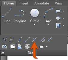
Figure 76: Point tool in the Ribbon
Command: POINT
Alias: PO
Points are objects that work as helpers that you can snap with the OSNAP Node option. The commands Divide and Measure (explained later in this section) create points along the selected object.
Points may become very difficult to see in the screen. To change how the points are displayed, click on the Point Style tool in the Utilities panel of the Home tab (Figure 77) or enter PTYPE and press Enter in the command window to show the Point Style dialog, and choose how you would like the point to be displayed.
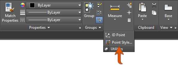
Figure 77: Point Style tool in the Ribbon
Note: Points are plotted as shown on screen; make sure to change the appearance to the desired style to avoid unnecessary replots of your drawings. Another option is to create points on a non-plotting layer such as the Defpoints layer (created automatically when dimensioning) or a custom, non-plotting layer (you will learn more about Layers in Chapter 4).
XLINE (Construction Line)
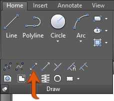
Figure 78: Construction Line Tool in Ribbon
Command: XLINE
Alias: XL
XLINE is a linear object with infinite length; it has no start point or end point. XLINES are ignored on Zoom Extend operations.
The XLINE prompts as follows:
Specify a point or [Hor/Ver/Ang/Bisect/Offset]:
Point: Specifies the points the XLINE passes through.
Hor or H: Creates an XLINE parallel to the current UCS X axis (perpendicular to the Y axis).
Ver or V: Creates an XLINE perpendicular to the current UCS X axis (parallel to the Y axis).
Ang: Allows the user to specify the XLINE angle measured counterclockwise from the X axis (by default).
Bisect: Creates an XLINE that bisects an angle selected by three points: vertex, start point, and end point of an imaginary arc.
Offset: Creates a XLINE that is parallel to an existing linear object with a given distance or through a selected point.
Ray
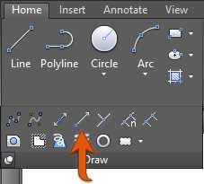
Figure 79: Ray tool in the Ribbon
Command: RAY
Rays are similar to XLINES with the difference that rays go infinitely in only one direction. If you trim an XLINE in one point, it will become a ray.
Divide
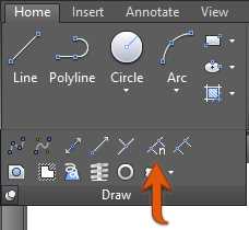
Figure 80: Divide tool in the Ribbon
Command: DIVIDE
Alias: DIV
Divide a geometric object (line, polyline, arc, circle, ellipse, or spline) in a given number of equal length segments. By default, the segment divisions are marked with Point objects.
The Divide command prompts are as follow:
Select object to divide:
Enter the number of segments or [Block]:
If choosing Block in the previous prompt, the following prompts are displayed:
Enter name of block to insert:
Align block with object? [Yes/No] <Y>:
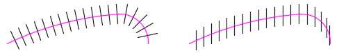
Figure 81: Block aligned with the object (left) and not aligned (right)
You will learn about blocks in Chapter 5.
Measure
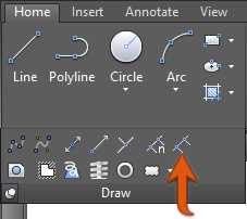
Figure 82: Measure tool in the Ribbon
Command: MEASURE
Alias: ME
Divides a geometric object (line, polyline, arc, circle, ellipse, or spline) in a number segments with given a given length. By default, the segments divisions are marked with Point objects.
The Measure and Divide commands work the same way. The only difference is that in the Divide command, the user enters the number of desired segments, and the segment length is calculated. In the Measure command, the user enters the desired segment length, and the number of divisions is calculated.
Display cleanup
Redraw
Command: REDRAW
Alias: R
Performs a quick display refresh in the active viewport and removes temporary graphic helpers.
Regen
Command: REGEN
Alias: RE
As your drawing gets bigger and you zoom and pan to many distinct areas of the drawing, eventually, when you zoom closer to a curved object, it may look faceted, and hatches may look broken. You also need to regenerate the drawing when changing Annotative Scale settings.
This is because AutoCAD readjusts the drawing to improve display performance, but does not readjust automatically. To do so, you run the Regen command to regenerate the entire drawing from in the active viewport as follows:
- Recalculate the locations and visibility for all objects
- Re-index the drawing database in order to optimize display and object selection performance
- Reset the overall area available for panning and zooming
RegenAll
Command: REGENALL
Alias: REA
Performs all Regen processes, but for all viewports in the space or layout.
- 1800+ high-performance UI components.
- Includes popular controls such as Grid, Chart, Scheduler, and more.
- 24x5 unlimited support by developers.