
AutoCAD Succinctly®

CHAPTER 6
Annotations
Adding notes and dimensioning is probably the most boring phase of the design process. Fortunately, AutoCAD provides the right tools to add annotation faster and in a very effective way.
In this chapter, you will learn about how to add notes to AutoCAD, including text, leaders, and tables. You will also learn how to spell check your notes and how to create text styles to use in your drawings.
You can work with annotation objects in the Annotation panel in the Home tab, and you have access to more powerful tools from the Annotate tab.
Figure 103 shows the Annotation panel located in the Home tab, from where you can open dialogs to define styles and set a current style.

Figure 103: Expanded Annotation Panel in the Home Tab
Annotative objects
Annotative objects allow you to create a single annotation object that can represent multiple sizes or scales (see Figure 104). Instead of creating multiple instances of the annotation object on different layers, you can enable the Annotative property of an annotation object and assign many drawing scales to the object.
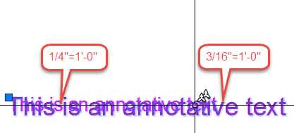
Figure 104: Annotative Text with two annotation scales assigned
The proper use of annotative objects increases your productivity and helps you avoid unnecessary errors when editing or removing annotative objects.
When creating annotative objects, the object size is scaled to match the current annotative scale.
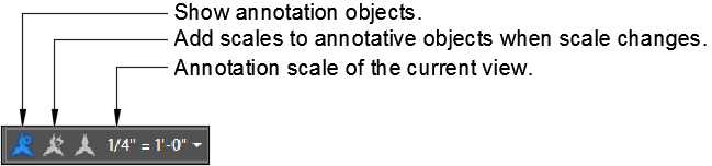
Figure 105: Annotative Controls in the Status bar
The annotative controls are the following:
Show annotation objects: When on (blue), all annotative objects are displayed independently if associated to the current annotation scale of the current view. Objects are displayed to the closest associated scale. When off (gray), only the annotative objects associated to the annotation scale of the current view are displayed.
Tip: Turn “Show annotation objects” on when working in model space and off in paper space. This will help you avoid creating annotative objects that already exist in the drawing, and all you have to do is assign the necessary scales.
Add scales to annotative objects when scale changes: When on (blue), all annotative objects are associated to the annotation scale when another scale is selected.
Annotation scale of the current view: Shows the current annotation scale. Click to select another annotation scale from a list, or edit/add annotation scales.
Add and delete annotation scales to objects:
- Select an annotative object and right-click.
- Click Annotative Object Scales.
- Add Current Scales: Add the current annotative scale to selected objects.
- Delete Current Scale: Remove the current annotative scale from selected objects. This option is only available if the object has more than one annotative scale associated.
- Add/Delete Scales: Opens a dialog box from which you can select multiple annotative scales to add or remove.
- Synchronize Multiple-scale Positions: Annotative objects can be stretched without affecting other scales assigned. This option repositions the scale to match the selected annotative scale.
Text
Text styles
Before you begin adding annotations, it’s important to set at least two text styles. Text Style is a library where AutoCAD stores text formats, such as text height and font information, for the many annotation purposes you may need. Ideally, you should create the text styles in the template file.
To create Text Style:
- Start a new drawing.
- From the Home Tab, expand the Annotation Panel and click the Text Style tool (see Figure 105) to open the Text Style dialog box.
- There is currently one style in the Styles list (Standard.) We are going to create some additional styles.
- Click the New… button to add a new style, enter Normal for the name and click OK to add the style.
- In the Font area, select:
- Font Name: Arial
- Font Style: Regular
- In the Size area:
- Make sure that Annotative is checked (a symbol appears next to the Style name indicating that the style is annotative).
- Height: 0.1 (this is the size of the font when plotted at 1:1 scale).
- In the Effects area:
- Make sure that Upside down is unchecked.
- Make sure that Backwards is unchecked.
- Set Width Factor = 1 and oblique Angle = 0.
- Click Apply.
- Click New… and enter DimTxt for the Style name and click OK.
- In the Font area, select:
- Font Name: Arial
- Font Style: Regular
- In the Size area:
- Make sure that Annotative is unchecked.
- Height: 0 (when Height is set to zero, the height is defined when creating the text).
- In the Effects area:
- Make sure that Upside down is unchecked.
- Make sure that Backwards is unchecked.
- Set Width Factor = 0.8 and oblique Angle = 0.
- Click Apply.
- Create additional Text Styles as follows:
Name | Font Name | Font Style | Annotative | Height | Width Factor | Oblique Angle |
Revision | Arial | Italic | Yes | 0.1 | 1 | 0 |
Title1 | Times New Roman | Bold | No | 0.25 | 1 | 0 |
Title2 | Times New Roman | Bold Italic | No | 0.16 | 1 | 0 |
Title3 | Times New Roman | Italic | No | 0.125 | 1 | 0 |
In the Styles list, select Normal and click Set Current to make Normal the current text style. Click Close to close the dialog box.
Now that you have a few text styles defined, you are ready to start adding notes to your drawings. The two most common types of text are single line text and multiline text.
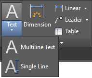
Figure 106: Text Tools
Single line text
Use single line text when creating basic texts, such as labels, that do not require advanced formatting.
Single line text creates a new line of text every time the Enter key is pressed. Each line of text is an independent object that you can edit as you wish without affecting the other lines.
Command: DTEXT
Alias: DT
Multiline text
Use Multiline Text to create paragraph texts objects. All lines and paragraphs are part of a single object that you can edit using the AutoCAD Text Editor.
Command: MTEXT
Alias: T or MT
When creating a multiline text, the Text Editor contextual tab is displayed in the ribbon, from which you can format the text similar to the way you would in Microsoft Word or other desktop text editor.
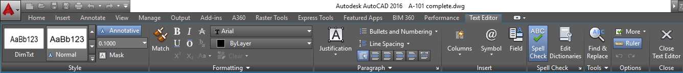
Figure 107: Text Editor contextual tab
If you explode a multiline text, it is converted to single line text, where each line of text is an independent object and all formatting is dismissed.
Text alignment
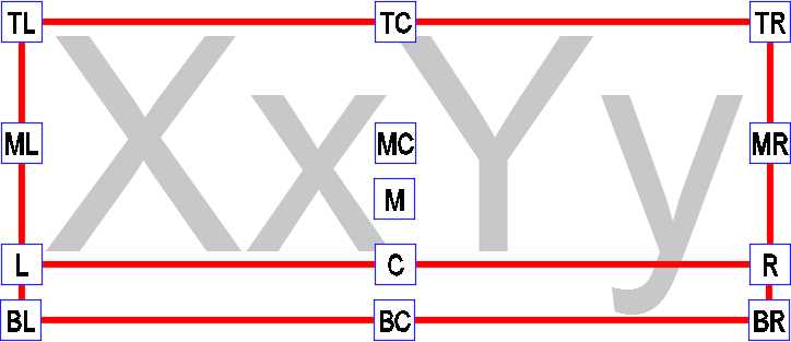
Figure 108: Text Alignment Base Points
TL = Top Left | TC = Top Center | TR = Top Right |
Create annotative text:
- From the Home tab, expand the Annotation panel and make sure that the active Text Styles annotative (annotative text styles show a small blue triangle shape). For this exercise, select the Normal text style.
- In the status bar, select the appropriate annotation scale (you can add additional annotation scales to the object later). Select 1/8”=1’-0” for this exercise.
Create annotative single line text:
- Continuing the previous drawing, create a new Layer named A-Anno-Note, color 231, continuous Line Type, Plotable (see the “Creating Layers” topic in Chapter 2 to review how to create a layer). Set A-Anno-Note as the current layer.
- Zoom so that the building fits in the drawing area.
- From the Home tab, Annotation panel, expand Text and select Single Line Text.
- Press F3 to turn Object Snaps off. The command window displays a message informing you of the Osnap state. If it reads <Osnap on>. press F3 again to turn it off.
- Click near the center of the big room area at the center of the building.
- Enter 0 and press Enter for the rotation angle of text.
- Enter Great Room, press Enter, FFL +7’-0”, and press Enter.
- Press Enter to finish the command.
- Select the text. Note that they are two independent objects.
Create annotative multiline text:
Single line text has no width limit, and the line continues until you press Enter to create a new line of text.
With multiline text, you can specify a width limit, and the line breaks automatically when it reaches the specified width.
- From the Home Tab, Annotation Panel, expand Text and select Multiline Text.
- Specify first corner: Click near the center of the garage area
- Specify opposite corner: Click a point so that the text box is nearly 125 units wide.
- Type Garage and press Enter, and type FFL +6’-6”. Do not press Enter; instead, click outside of the text box to finish the command.
- Select the multiline text; the text is a single object with two lines.
Import existing text to multiline text
- Double-click the middle button of the mouse to zoom extend.
- From the Home tab, Annotation panel, expand Text and select Multiline Text.
- Click a blank area to the left of the site.
- In the command window, enter W and press Enter to specify the textbox width.
- Enter 550 and press Enter for the width.
- From the Text Editor contextual tab, expand the Tools panel and select Import Text.
- Browse to Chapter 06 folder of this book’s exercises, and select the MText.txt file.
- Click Open.
- The text was imported into the textbox.
- Click outside of the textbox to finish the command.
The steps to create non-annotative text are the same as creating annotative text, but you need to make sure to select a text style that is not set as annotative, and you may be required to specify the text height on screen.
Edit texts
Command: TEXTEDIT
Alias: ED
To edit a text, just double-click the text object or select the annotation object to be edited, type ED in the command window, and press Enter or the Spacebar.
Note: If TEXTEDIT is executed with no annotation object selected, AutoCAD prompts to select an annotation object to be edited.
Text masking
Sometimes text becomes difficult to read if it’s overlapping other objects. Multiline text can be easily masked so that background elements are hidden and the text becomes readable.
To illustrate this, copy the multiline text added in the garage to over the driveway area to the right. Double-click to edit the text, and replace Garage with Driveway. Click outside of the text area to commit.
The text is really difficult to read over the hatch pattern. Follow these steps to mask it:
- Select the multiline text.
- Right-click and choose Properties from the contextual menu to open the Properties palette.
- In the Properties palette, under Text group, find Background mask.
- Click the No text, and then click the small icon to the right of the field, as shown in Figure 109.
- In the Background Mask dialog box, select Use background mask and Use drawing background color.
- Enter 1.25 in the Border offset factor textbox. This is the gap distance from the text to the mask border relative to the text size.
- Click OK to apply the setting and close the dialog box.
- In the command window, type REGEN and press Enter to regenerate the drawing.
- Use Grip mode to adjust the text box width.
- Save and close your drawing.
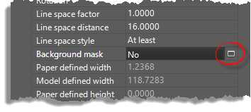
Figure 109: Mtext Background Mask
Dimensions
A design is not complete without dimensions. Dimensions are a critical part of the design process and must be easy to read and precise.
You need to add dimensions on virtually every type of project, from concept to production and construction drawings. AutoCAD includes the right tools to help you to make dimensioning a smooth design process.
Dimension styles
Dimension style is a set of parameters saved within the drawing where you define all standard properties, from lines to unit formats.
Command: DIMSTYLE
Alias: D
To create or edit dimension styles from the Home tab, expand the Annotation panel and click on the Dimension Style icon (see Figure 103) or type DIMSTYLE in the command window and press Enter or Spacebar to open the Dimension Style Manager dialog box.
The Styles list (the box to the left) shows all dimension styles available in the current drawing. When you select a dimension style in the list, the preview is displayed in the preview box.
To create a new Dimension Style, click New…, to the right of the dialog box, to open the Create New Dimension Style dialog box:
New Style Name: Enter the name for the new style.
Start With: Allows you to select a style to be used as template.
Annotative: Allows the user to define if the new dimension style is annotative.
Use for: Allows the user to define which type of dimension the new style is to be applied to. For example, you can create a set of parameters to be used only for angular dimensions. When a specific type of dimension is selected, the new name is not available and the new style becomes a sub-style of the dimension selected in the Start with dropdown list.
Create a dimension style as follows:
- New Style Name: MyDimStyle
- Start with: Standard
- Annotative: Yes (checked)
- Used for: All dimensions
Click Continue. The Dimension Style Editor (Figure 110) is loaded, and you can start configuring your new dimension style.
The Dimension Style Editor (New, Modify, and Override Dimension Style Dialog Boxes) is composed of seven tabs:
- Lines: Controls the appearance of all lines in the dimension.
- Dimension lines: The lines where the dimension text is located.
- Extension lines: The lines from the object being dimensioned to the dimension line.
- Symbols and Arrows: Controls the appearance of arrowheads and center marks.
- Text: Controls the appearance, location, and alignment of the text to be placed in the dimension style.
- Fit: Controls how text and arrows are to be placed.
- Primary Units: Controls the dimension unit format.
- Alternate Units: Allows the user to define a second unit for the dimension. For example, assuming you have the primary unit set to the Architectural format (feet and inches), you can set an alternate unit to show the dimension in centimeters.
- Tolerances: Controls the appearance of text in tolerances.
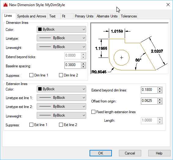
Figure 110: Dimension Style Editor
Continuing with our dimension style:
- Select the Lines tab:
- Dimension lines:
- Color, Linetype, and Lineweight: ByBlock
- Baseline spacing: 0.2
- Suppress: both unchecked
- Extension Lines
- Color, Linetype, and Lineweight: ByBlock
- Extend beyond dim lines: 0.1
- Offset from origin: 0.5 (This is the distance from the deflection point to the extension line.)
- Suppress: both unchecked
- Select the Symbols and Arrows tab:
- Arrowheads:
- First: Architectural tick
- Second: Architectural tick
- Leader: Closed filled
- Arrow size: 0.1
- Select the Text tab:
- Text appearance:
- Text style: DimTxt
- Text color: Green
- Fill color: Background (This is like the mask used on Multiline Text in the previous topic.)
- Text height: 0.1
- Text placement:
- Vertical: Above
- Horizontal: Centered
- View Direction: Left-to-Right
- Offset from dim line: 0.05
- Text alignment: ISO standard
- Select the Primary Units tab:
- Linear dimensions:
- Unit format: Architectural
- Precision: 0’-0 1/16”
- Fraction format: Horizontal
- Click OK to add the dimension style and close the dialog box.
- In the Dimension Style Manager, select MyDimStyle in the Styles list and click the Set Current button.
- Click Close to close the Dimension Style Manager.
- Save the drawing.
Edit dimension styles
To Eedit an existing dimension style, open the Dimension Style Manager, select the dimension style to be edited, and click the Modify… button. When you done editing, click OK to commit the changes and close the dialog box, or click Cancel to discard all changes and close the dialog box.
After all dialog boxes are closed, AutoCAD regenerates the drawing to apply the changes to existing dimensions associated to the edited style.
Dimensioning the drawing
You can work with dimensions from the Annotation panel in the Home tab, or for more advanced tools, from the Dimensions panel in the Annotation tab. There are basically seven basic types of dimensions:
- Linear: Linear dimensions are vertical or horizontal dimensions matching the current UCS orientation.
- Aligned: Aligned dimensions are linear dimensions on which the dimension line is rotated to the direction of the extension lines origin points.
- Radius: Radial dimensions that measure circles’ and arcs’ radii. Jogged is a Radial dimension that you can use to jog the dimension line.
- Diameter: Radial dimension that measures the diameter of circles, and although not commonly used, arcs.
- Angular: Measures the angle of selected objects or by specifying three points (vertex, angle start point, and angle end point).
- Ordinate: Measures the vertical or horizontal distance from the UCS origin point.
- Arc Length: Measures the length of arcs.
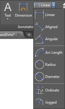
Figure 111: Dimensions Tools
Baseline and continued dimensions
Baseline and Continued are dimension commands that support continuing to dimension from a previously created dimension or by selecting an existing one.
Continue Dimension creates a new dimension starting from the second dimension line of the previously created dimension.
Baseline Dimension creates new dimensions where all subsequent dimensions start from the first extension line of previously created dimensions, and are spaced by the value specified in the baseline spacing set in the dimension style.
To jumpstart dimensioning, open the Column Base Notes drawing located in the Chapter 06 folder. This is the same drawing created and edited in previous exercises, but on this one, I have added a dimension style named Dim with Alternate Unit. This dimension style includes a primary unit in architectural units, and an alternate unit in millimeters. Feel free to open it in the Dimension Style Editor to review the properties.
Let’s add some dimensions to the column base:
- Make sure that Osnap is on. You can press F3 anytime to toggle Osnap as needed.
- From the Home tab, Annotation panel, select the Linear dimension tool.
- Click near the lower-left corner of the column base. Make sure that snaps to the end point.
- Click the end point immediately above.
- Move the cursor left and click to place the dimension line.
- Activate the Annotate tab in the ribbon.
- From the Dimensions panel, select Baseline.
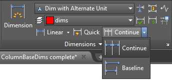
Figure 112: Dimensions Panel in the Annotate Tab
- Select each end point of the column base transition sequentially, up to the top-most point.
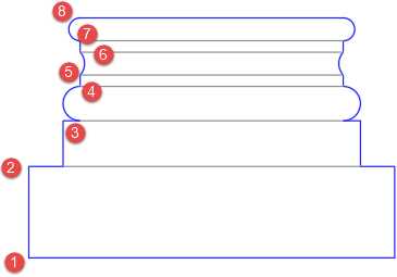
- Press Enter, Spacebar, or Esc to finish the command.
- Select the Linear dimension tool.
- Select the lower-left end point of the column base.
- Select the end point of the lower-left corner of the column base second level.
- Move the cursor down so that the dimension line is horizontal. Click to place the dimension below the column base.
- Select the end point to the right of the second level of the base, and then the lower-right corner of the base.
- Select the Linear dimension tool.
- Select the points 1 and 4 shown in the following figure.
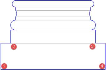
- Move the cursor down and select a point to place the dimension line below the existing horizontal dimensions.
- Save your drawing.
Multileader
Multileader is an annotation object used to create text with leader lines.

Figure 113: Multileader
Multileader styles
To create or edit Multileader Styles from the Home tab, expand the Annotation panel and click on the Multileader Styles icon (see Figure 103) to open the Dimension Style Manager dialog box.
The Styles list (the box to the left) shows all multileader styles available in the current drawing. When you select a dimension style in the list, the preview is displayed in the preview box.
To create a new multileader style, click the New… button, to the right of the dialog box, to open the Create New Multileader Style dialog box:
New Style Name: Enter the name for the new style.
Start With: Allows you to select a style to be used as template.
Annotative: Allows you to define if the new dimension style is annotative.
In the Column Base Notes drawing, create a Multileader Style as follows:
- New Style Name: MyMultileader
- Start with: Standard
- Annotative: Yes (checked)
- Used for: All dimensions
Click Continue.
The Multileader Styles Editor is loaded, and it consists of three tabs:
- Leader Format: Settings to control the appearance of the leader line and arrowhead.
- Leader Structure: Settings to deal with the leader format.
- Content: Settings to control the multileader contents. You can choose from Mtext, Block, or none (leader only).
Continuing with our new Multileader Style configuration:
- In the Leader Format tab:
- General:
- Type: Straight
- Color, Linetype, and Lineweight: ByBlock
- Arrowhead:
- Symbol: Closed filled
- Size: 0.1 (because of the drawing units setting, the value will be automatically converted to inches)
- In the Leader Structure tab:
- Constraints
- Maximum leader points: Checked, 2 (this will limit the leader line to two points)
- First and second segment angle: Unchecked
- Landing Settings:
- Automatically include landing: Checked
- Set landing distance: Checked
- Landing distance: 0.25 (you can adjust the landing distance using grips after the leader is created)
- Scale:
- Annotative: Checked
- In the Content tab:
- Multileader type: Mtext
- Text Options:
- Text Style: Normal
- Text angle: Keep horizontal
- Text Color: Blue
- Always left justify: Checked
- Frame text: Unchecked
- Leader connection:
- Horizontal attachment: Checked
- Left attachment: Middle of top line
- Right attachment: Middle of top line
- Landing gap: 0.5 (this value also affects the text frame offset)
- Click OK to save the changes and close the dialog box.
- Select the MyMultileader style and click Set Current.
- Click Close.
Adding leaders
You can work with leader from the Annotation panel in the Home tab or from the Leaders panel in the Annotate tab.
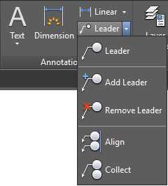
Figure 114: Multileader tools in the Annotation Panel
- Open the Column Base Notes drawing, if not opened.
- Click the Leader tool in the Annotation panel.
- Right-click the mouse and choose Geometric center from the Object Snap Override menu.
- Move the crosshair near the column base perimeter. Make sure it is snapping to the center of the column base and click.
- Move the cursor to the right of the drawing and click to place the multileader.
- Type: Cast stone finish 8 Color TBD
- Press Ctrl+Enter or click anywhere outside of the text box.
- Select the Add Leader tool.
- Select the multileader object.
- Add two more leaders, above and below the existing leader.
- Press Enter, Spacebar, or Esc to finish the command.
- Click the Leader tool in the Annotation panel.
- Click near the mid-point of the lowest right vertical line of the column base.
- Move the mouse to the right and click to place the leader.
- Type: Structural by others
- Press Ctrl+Enter to finish.
- Save your drawing.
Chapter summary
In this chapter, you learned about how to add notes to the drawing. You created text styles, dimension styles, and leader styles, and also added notes to the drawing.
Drawing notes are critical in a drawing. This is how you communicate your ideas and the production requirements of your product.
- 1800+ high-performance UI components.
- Includes popular controls such as Grid, Chart, Scheduler, and more.
- 24x5 unlimited support by developers.