
Assembly Language Succinctly®

CHAPTER 8
SIMD Instruction Sets
SIMD stands for Single Instruction, Multiple Data. It is a type of parallel programming. The idea of SIMD is to perform the same instructions on multiple pieces of data at once. The SIMD instructions added to the x86 architecture were originally used to speed up multimedia processing. It is common in multimedia programming to perform the same operation for every pixel on the screen or perhaps every byte in a stream of sound data.
Since its introduction, hundreds of new instructions have been added to x86 CPUs. It is a very different way to program. It requires a new set of eyes, debugging skills, new algorithms, and data structures. The SIMD instruction sets have their own new registers and instructions. These new registers are often larger than the original x86 registers, and they can be thought of as holding a small array of values. For instance, a 64-bit SIMD register can hold an array of 8 bytes, 4 words, or 2 dwords.
Many of the SIMD style instructions operate on corresponding elements in two registers. Addition of bytes in SIMD involves adding the two lowest bytes from both operands and storing the answer in the lowest byte, adding the two second-to-lowest and storing this in the second lowest byte of the answer—this goes on until the two top bytes are added together, and their result is stored in the top element of the answer. Although many instructions work in this manner, just as many do something completely different.
As an example, consider a loop in scalar programming which adds the elements from two arrays. Perhaps the arrays contain 8 elements. The elements might be added with C++ as follows:
for(int i = 0; i < 8; i++) { arr1[i] += arr2[i]; } |
This results in around twenty-four lines of assembly being generated when optimizations are switched on in Visual Studio. The C++ compiler unrolls the entire loop and uses eight ADD instructions. Unrolling loops is a good optimization technique, and modern compilers are experts at exactly this kind of optimization.
However, using even the most basic SIMD instructions (MMX is used in this example), the same addition of 8-byte arrays can be accomplished in just four instructions.
movq mm0, qword ptr arr1 ; Load 8 bytes from arr1 into MM0 paddb mm0, qword ptr arr2 ; Add the 8 bytes from arr2 movq qword ptr arr1, mm0 ; Store the answer back in arr1 emms ; Close multimedia state |
The most important thing to note is that there is no loop in the SIMD version. All eight iterations of the loop can be carried out in a single instruction (PADDB, the add packed bytes instruction). The addition instruction is a single step for the CPU; it takes one or two clock cycles (depending on the CPU and pipeline issues, and assuming the arrays are in cache). MMX can perform eight operations at once, but it will not perform eight times the speed of regular scalar code. While it won’t perform eight times faster, you will see a performance increase, particularly with compute-intensive functions. Compute-intensive functions are those that load data from RAM, perform many operations on the data, and then store the results.
SIMD Concepts
Saturating Arithmetic versus Wraparound Arithmetic
In the regular x86 instructions, when a result is too large to fit into the destination, the top of the result is lost and only the bits that do fit into the destination are actually written. This effectively wraps the results around at the top and bottom, such as the following:
mov al, 255 inc al ; AL will wrap around to 0 since 256 is too large mov al, 0 dec al ; AL will wrap to 255 if unsigned and -1 if signed |
This is called wraparound arithmetic, or modular arithmetic. It is often all that is needed, but there are some problems. Many operations on multimedia do not benefit from this type of arithmetic. For example, consider an algorithm to increase the brightness of an image by adding some value to each pixel. Some of the pixels may already be almost white, having a value near 255, 255, 255, which is a white pixel in the standard RGB24 color modes. If the extra brightness is added to these pixels, they will suddenly go very dark. Our original pixel has a value of 252 for its red component, we add 12 to the brightness to make 264, but due to wrapping round at 256, we will end up with 8. Our pixel will go from very light to very dark, making the adjust brightness algorithm appear incorrect.
For this exact reason, saturating arithmetic was incorporated into many instructions in the SIMD instruction sets. Saturating arithmetic sets a maximum and minimum value for each of the data types, and instead of wrapping around, the answer will be capped at these values. The 252 + 12 in our example would be saturated to 255.
Each data size and type (unsigned or signed) has two saturating values: one is the minimum and the other is the maximum.
Table 18: Saturating Values
Data Type | Minimum Saturate | Maximum Saturate |
|---|---|---|
Unsigned Byte | 0 | 255 |
Signed Byte | -128 | 127 |
Unsigned Word | 0 | 65535 |
Signed Word | -32768 | 32767 |
Unsigned Dword | 0 | 4294967295 |
Signed Dword | -2147483648 | 2147483647 |
Packed/SIMD versus Scalar
Operations on more than one data element at once are called SIMD or packed operations. Operations on single elements, as in the x86 instructions, are called scalar. Some of the SIMD instruction sets perform scalar operations as well as SIMD.
MMX
MMX was the first SIMD instruction set added to the x86 architecture. It was added by Intel in 1996 (other x86 CPU manufacturers also include these SIMD instruction sets such as AMD and VIA). At the time it was added, Intel did not wish to add new registers to the CPUs. Instead, they used the same registers as the x87 floating point unit (the MMX registers are said to be aliased to the x87 registers and vice versa). The x87 floating point unit has a dual role; it can perform its regular x87 floating point arithmetic or it can be in its multimedia mode, performing MMX instructions. The x87 unit will change to MMX mode simply by executing an MMX instruction, but once the program is finished with MMX, you have to call the EMMS (exit multimedia state) instruction to have the x87 return to its regular floating point mode.
It is important to note that the MMX instructions were also added to the SSE2 instruction set. When using these instructions with the SSE registers, they perform double the workload, working with 128-bit SSE registers instead of the 64-bit MMX registers. Most of the SSE instruction sets work with floating point, but you can also use any of the MMX instructions in conjunction with 128-bit SSE registers to perform operations on integers if the CPU is SSE2 capable. Almost all CPUs today are SSE2 capable. Windows 8 and Office 2013 require SSE2 capable CPUs, which indicates how widespread SSE2 CPUs are. Where the difference between the MMX and SSE2 versions of the instruction is important, I have included the instruction in both the MMX and the SSE reference sections.
Registers
There are eight MMX registers aliased to the x87 registers (ST0 to ST7). We will not examine x87 in this book, since SSE has made it mostly legacy. The MMX registers are named MM0, MM2, MM3, MM4, MM5, MM6, and MM7. Each register is 64 bits wide. An MMX register can be used as 8 bytes, 4 words, 2 dwords, or occasionally a single qword. The size of data that an MMX register is being used for is dictated by the instruction. The data size a particular register is holding is not fixed; you are free to change it whenever you need to. Traditionally, the registers are drawn as arrays with the first byte on the far right and the last one on the left. The bytes in each element are also an array of bits, with the least significant bits on the right of each element and the most significant bits on the left.
The MMX registers can be used in the following ways:
8 bytes | ||
4 words | ||
2 Dwords | ||
1 Qword |
|
Most MMX instructions take two operands; the first is the destination and the second is the source. Like the x86 instructions, the destination often also acts as a source. For instance, with the add instructions, the destination becomes the destination plus the source. Since this might be misleading, I will use the terms operand 1 and 2 or parameter 1 and 2.
Referencing Memory
To reference memory in an MMX instruction, use the following:
movq mm5, qword ptr [A] |
A is an array of at least 64 bits. You cannot use A by itself (without the pointer prefix); MMX needs to know there is a qword of data there. You can also use the x86 complex addressing modes.
mov mm0, qword ptr [rax+rdx*2] mov qword ptr [rdx], mm3 |
Most MMX (and SSE as well) instructions do not allow for the first operand to be memory. Usually, the first operand must be an MMX register and the second can be either a MMX register or a memory operand.
Exit Multimedia State
EMMS
The eight MMX registers physically use the floating point unit's ST(x) registers. As soon as an MMX instruction is executed, the CPU enters multimedia state, or MMX mode. To resume regular floating point use for these registers, you must call EMMS.
movq mm0, mm1 ; Call some MMX instruction to begin MMX mode emms ; After you are done in MMX, call emms to restore floating point mode |
Note: Almost all floating point arithmetic is performed by using the SSE scalar instructions instead of the rather lonesome and increasingly neglected x87 unit. In x64, not calling EMMS will usually not cause a problem. EMMS is always a good idea though, since it may be difficult to track the bugs that this type of heinous neglect of good practices would instantiate.
Do not call EMMS in the middle of a loop, since (particularly on older Intel CPUs) the instruction is quite slow to execute. It is better to do large chunks of MMX processing together and call this instruction only once all MMX processing is complete.
Moving Data into MMX Registers
There are two data movement instructions in MMX; one moves 64 bits of data and the other moves 32 bits. When moving 32 bits, if the destination operand is an MMX register, the top is cleared to 0 and the data is only moved into the bottom half.
Move Quad-Word
MOVQ [mmx], [mmx/mem64]
MOVQ [mmx/mem64], [mmx]
This instruction copies 64 bits of data from the second operand into the first.
Move Dword
MOVD [mmx], [mmx/mem32/reg32]
MOVD [mmx/mem32/re32], [mmx]
This instruction moves 32 bits from the second operand into the bottom of the MMX register first operand; it can also be used to move 32 bits of data from a general purpose register or memory location to an MMX register.
Note: When the first operand is an MMX register, this instruction clears the top 32 bits to 0.
mov eax, 12
mov mm0, eax ; MM0 would have the following dwords: [0, 12]
Boolean Instructions
PAND [mmx], [mmx/mem64]
POR [mmx], [mmx/mem64]
PXOR [mmx], [mmx/mem64]
PANDN [mmx], [mmx/mem64]
These instructions apply the Boolean operation between the bits of the two operands and store the result in the first operand.
Packed AND NOT (PANDN) has no x86 equivalent; it performs a bitwise AND with the source and the inverse (bitwise NOT) of the destination (first operand). The first operand is complemented, then has the AND performed with the second operand. For truth tables of the other bitwise instructions, please consult the entries for OR, AND, and XOR in the x86 instruction set.
Table 19: Truth Table for PANDN
Operand 1 | Operand 2 | Result in Operand 1 |
0 | 0 | 0 |
0 | 1 | 1 |
1 | 0 | 0 |
1 | 1 | 0 |
Note: To clear an MMX register to 0, you can use PXOR with the register to clear as both operands.
pxor mm0, mm0 ; Clear MM0 to 0
pandn mm0, mm0 ; The new ANDN instruction will clear a register to 0
There is no difference between the data types when using the Boolean instructions. Using XOR on data in words produces exactly the same result as using XOR on data in bytes. Unlike many other instructions, the Boolean instructions do not have any specified data types.
Shifting Bits
PSLLW [mmx], [mmx/mem64/imm8] ; Left, Logical, Words
PSLLD [mmx], [mmx/mem64/imm8] ; Left, Logical, dwords
PSLLQ [mmx], [mmx/mem64/imm8] ; Left, Logical, qword
PSRLW [mmx], [mmx/mem64/imm8] ; Right, Logical, Words
PSRLD [mmx], [mmx/mem64/imm8] ; Right, Logical, dwords
PSRLQ [mmx], [mmx/mem64/imm8] ; Right, Logical, qword
PSRAW [mmx], [mmx/mem64/imm8] ; Right, Arithmetic, Words
PSRAD [mmx], [mmx/mem64/imm8] ; Right, Arithmetic, dwords
These instructions shift the elements in the destination right or left by the number of bits specified in the second operand. Left shifting effectively multiplies data by a power of two, while right shifting shifts the bits right, and divides by a power of two.
Logical shifts move 0 into the vacant spots, while the arithmetic right shifts duplicate the sign bit and can be used for signed division of integers by powers of two.
Note: If the second operand is a 64-bit memory location or an MMX register, it is not read SIMD style. It is read as a single 64-bit number. You cannot shift the individual elements in an MMX register by different amounts; they are all shifted the same number of bits.
The shifting instructions do not wrap data around, so you can clear a register to 0 by shifting left more bits than the data size, and shifting left 64 bits or more clears the register to 0.
You can also copy the sign of elements across the entire element by using the arithmetic right shifts and a value greater or equal to the data element size.
psraw mm0, 16; Sets each of MM0's words to 1s if negative, otherwise 0 |
Arithmetic Instructions
PADDB [mmx], [mmx/mem64] ; Add unsigned/signed bytes, wrap around
PADDSB [mmx], [mmx/mem64] ; Add signed bytes, saturate
PADDUSB [mmx], [mmx/mem64] ; Add unsigned bytes, saturate
PADDW [mmx], [mmx/mem64] ; Add unsigned/signed words, wrap around
PADDSW [mmx], [mmx/mem64] ; Add signed words, saturate
PADDUSW [mmx], [mmx/mem64] ; Add unsigned words, saturate
PADDD [mmx], [mmx/mem64] ; Add unsigned/signed double-words, wrap around
PSUBB [mmx], [mmx/mem64] ; Subtract signed/unsigned bytes, wrap around
PSUBSB [mmx], [mmx/mem64] ; Subtract signed words, saturate
PSUBUSB [mmx], [mmx/mem64] ; Subtract unsigned bytes, saturate
PSUBW [mmx], [mmx/mem64] ; Subtract unsigned/signed words, wrap around
PSUBSW [mmx], [mmx/mem64] ; Subtract signed words, saturate
PSUBUSW [mmx], [mmx/mem64] ; Subtract unsigned words, saturate
PSUBD [mmx], [mmx/mem64] ; Subtract signed/unsigned doubles
These instructions add and subtract bytes, words, or dwords. Each element in the second operand is subtracted from or added to the corresponding element in the first operand, and the results from the packed additions and subtractions are stored in the first operand. These instructions have the option to use wrap around or saturation arithmetic. There are no saturation or unsigned instructions that operate on dwords in MMX; if this functionality is required, then use SSE.
There is an instruction for each data type where it does not matter if the data type is signed or unsigned, since the result is the same. PADDB, PADDW, PADDD, PSUBB, PSUBW, and PSUBD all give the same answer if the data is signed or unsigned. None of them use saturation.
Note: When you need to detect what elements overflowed in SIMD operations, you can perform both the saturating version of the operation and the wrap around version, and compare the results. Any elements that are not identical in both answers have overflowed. This is useful because there is no carry flag or overflow available in SIMD.
The instruction PADDW mm0, mm1 is illustrated as follows:
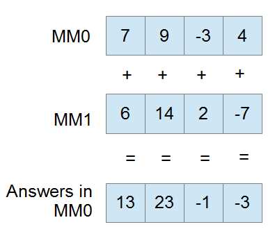
Figure 16
The next example is of PSUBW mm0, mm1. Note the second operand is subtracted from the first.
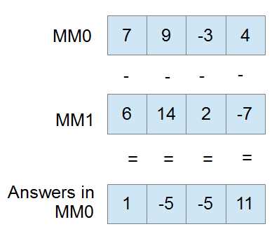
Figure 17
Multiplication
PMULHW [mmx], [mmx/mem64] ; Multiply and keep high 16 bits of 32 bit result
PMULLW [mmx], [mmx/mem64] ; Multiply and keep low 16 bits of 32 bit result
PMADDWD [mm0], [mmx/mem64] ; Multiply and add words to double-words
You can multiply two MMX registers or an MMX register with a memory location, but all these instructions only operate on signed words. For multiplication of other integer data types, use SSE2. When multiplying, you can choose to keep either the top 16 bits (PMULHW) or the bottom 16 bits (PMULLW) of the multiplication.
There is also a fused multiply add instruction (PMADDWD, assumed words are signed) that allows you to multiply and add in a single operation with added precision. Each word in the destination is multiplied by the corresponding word in the destination to give four results: A, B, C, and D. A is then added to B, C is added to D, and both these answers form the final two dwords in the destination. The initial multiplication is able to result in 32 bits since a larger temporary register is used.
Note: If one of your operands for the PMADDWD is { 1, 1, 1, 1 } (four words all set to 1), the operation performs a horizontal add. It adds each adjacent pair of words in the destination and stores the two results as two dwords.
Note: If every second word in both operands to a PMADDWD is 0, then the instruction will result in two word multiplication, but the entire 32-bit result will be kept.
Comparisons
pcmpeqb [mmx], [mmx/mem64] ; Compare bytes for equality
pcmpgtb [mmx], [mmx/mem64] ; Compare signed bytes for greater than
pcmpeqw [mmx], [mmx/mem64] ; Compare words for equality
pcmpgtw [mmx], [mmx/mem64] ; Compare signed words for greater than
pcmpeqd [mmx], [mmx/mem64] ; Compare double-words for equality
pcmpgtd [mmx], [mmx/mem64] ; Compare signed double-words for greater than
MMX has a comparison instruction for testing equality and greater-than only. All other comparisons must be built from these and the Boolean instructions.
Comparisons in MMX (and the other SIMD instruction sets) result in setting all of the bits of each element to either 1 or 0. Elements are set to a mask of all 1s where they pass the condition and all 0s where they do not. All “greater than” comparisons are signed in MMX.
For instance, if mm0 has { 9, 14, 21, 40 } as four words, and MM1 has { 9, 4, 21, 4 }, then the following code will result in MM0 having { ffffh, 0000h, ffffh, 0000h }:
pcmpeqw mm0, mm1 ; Packed compare words for equality
This is because there are two words that are the same in MM0 and MM1, and two that are not the same. MM0 effectively becomes a mask of words that are the same between MM0 and MM1.
Note: The PCMPEQB instruction (and the other equality comparison instructions) can be used to set an MMX register to all 1s or ffffffffffffffffh by using the same register as both operands.
pcmpeqb mm0, mm0 ; Set MM0 to all 1s
Creating the Remaining Comparison Operators
There are a number of ways to create the other comparisons (!=, >=, etc.). To perform the not-equal operation (!=) between MM0 and MM1 using MM7 as a temporary register, use the following:
pcmpeqb mm0, mm1 pcmpeqb mm7, mm7 pxor mm0, mm7 |
To perform the greater than or equal to operation (>=) between MM0 and MM1 using MM7 as a temporary register, use the following:
movq mm7, mm0 ; Backup parameter to mm7 pcmpeqb mm0, mm1 ; Find where they are equal pcmpgb mm7, mm1 ; Find where they are greater por mm0, mm7 ; OR these two results |
To perform the less-than operation (<) between MM0 and MM1 using MM7 as a temporary register, use the following:
movq mm7, mm0 ; Backup parameter to mm7 pcmpeqd mm0, mm1 ; Does mm0 = mm1 ? pcmpgd mm7, mm1 ; Is mm7 > mm1 ? por mm0, mm7 ; mm0 is now >= mm1 pcmpeqd mm7, mm7 ; Get mm7 ready to complement mm0 pxor mm0, mm7 ; mm0 is now < mm1 |
Packing
PACKSSDW [mmx], [mmx/mem64] ; Pack signed double-words to words and saturate
PACKSSWB [mmx], [mmx/mem64] ; Pack signed words to bytes and saturate
PACKUSWB [mmx], [mmx/mem64] ; Pack unsigned words to bytes and saturate
Packing instructions convert large data types into smaller ones, and then take the elements of two operands and resize them so that they fit into a single operand. You can convert dwords to words or words to bytes. You can use signed or unsigned words when converting bytes. All the MMX packing instructions use saturation.
PACKSSDW converts dwords to words by saturating the dwords and storing the two converted dwords from the first operand in the lower half of the answer, and storing the two converted words from the second operand in the upper half of the answer.
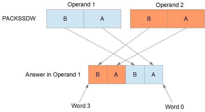
Figure 18
PACKSSWB and PACKUSWB convert words to bytes by first applying saturation. The PACKSSWB range is -128 to 127, and the PACKUSWB range is 0 to 255. The four words from the first operand are converted to bytes and stored in the lower half of the answer, and the four words from the second operand are converted to bytes and stored in the upper half of the answer.
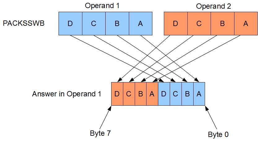
Figure 19
Unpacking
PUNPCKLBW [mmx], [mmx/mem64] ; Unpack low bytes to words
PUNPCKHBW [mmx], [mmx/mem64] ; Unpack high bytes to words and interleave
PUNPCKLWD [mmx], [mmx/mem64] ; Unpack low words to double-words
PUNPCKHWD [mmx], [mmx/mem64] ; Unpack high words to double-words
PUNPCKLDQ [mmx], [mmx/mem64] ; Unpack low double-words to quad-words
PUNPCKHDQ [mmx], [mmx/mem64] ; Unpack high dwords to qword and interleave
The unpacking instructions convert from smaller data types to larger ones. They are MOV instructions, as there is actually no data conversion at all. For example, converting the eight bytes in the source to eight words would require more space than can fit in an MMX register, so you must choose to convert either the lower or upper half.
The conversion is performed using what is called interleaving. Elements from the first operand are interleaved with those from the second operand.
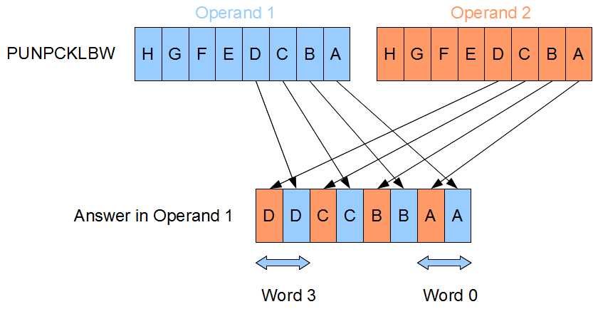
Figure 20
The interleaving system was invented to allow the greatest flexibility while adding the fewest number of instructions to the CPU. If the second operand contains all zeros, then these instructions have the effect of zero-extending (unsigned extending) the data in the first operand.
Initially, these instructions were also used to broadcast values (duplicate elements across the whole register). However, the SSE shuffle instructions make broadcasting a lot easier.
Some examples of using the packing and unpacking instructions are as follows:
; To duplicate the bottom 32 bits of mm0 into the top: punpckldq mm0, mm0 ; To fill MM0 with 8 copies of a byte from AL (9 in this example): xor eax, eax ; Make sure the top of EAX is 0 mov al, 9 ; Copy the byte into eax, 9 in this example movd mm0, eax ; Copy eax to the low dword of mm0 punpckldq mm0, mm0 ; Duplicate the bottom into the topof MM0 packssdw mm0, mm0 ; Copy these two 9s into 4 packuswb mm0, mm0 ; Copy those four 9s into 8 ; Sign extending: If the second operand contains the signs of the ; elements in the first operand (use the PSRAW instruction to get this) ; then these instructions have the effect of sign extending the data ; in the first operand: movq mm1, mm0 ; Copy words psraw mm1, 16 ; Fill mm1 with signs of elements in mm0 punpcklwd mm0, mm1 ; Unpack interleaving with signs, sign extend to dwords! |
SSE Instruction Sets
Introduction
The SSE (Streaming SIMD Extensions) instruction sets perform SIMD operation on new 128-bit registers. Over the years, SSE, SSE2, SSE3, SSSE3, SSE4.1, SSE4.2, and SSE4a instruction sets have been created. The original SSE instruction set's purpose was to allow SIMD floating point instructions and the ability to work on four single-precision floating point values at once. The additional instruction sets added a multitude of instructions for doing almost anything in both SIMD and scalar. For instance, the SSE2 instruction set added integer instructions as well as many double-precision floating point instructions.
Where MMX registers were aliased to the x87 unit's registers, the SSE registers occupy a new register space on the CPU. There is no need to switch from multimedia mode to floating point when using SSE. Some of the SSE instructions do use the MMX registers in conjunction with the SSE registers, and these instructions still cause a switch in the x87 unit. Just as in the MMX instruction set, whenever an SSE instruction references the MMX registers, EMMS must be called to restore the x87 unit to floating point mode.
Originally there were eight SSE registers named from XMM0 to XMM7. In x64 applications, this has been increased to sixteen registers named from XMM0 to XMM15. Each SSE register is 128 bits wide and can be used for the data sizes shown in Figure 21.
In the instruction listings that follow, I have included the instruction sets (beside the mnemonics). This is where the instructions come from. Be sure to check that the CPU is capable of an instruction with the CPUID Function 1 prior to using it.
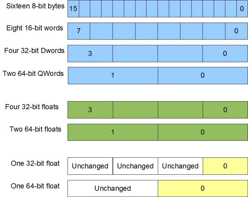
Figure 21
Collectively, the SSE instruction sets present a programmer with a staggering array of instructions numbering in the hundreds. Many instructions have scalar as well as SIMD versions.
Note: The Microsoft compiler users scalar SSE instructions to perform floating point operations, instead of using the x87 FPU.
In x64, the C calling convention used by the C++ compiler passes floating point parameters using the XMM0 register. Only the lowest single or double precision element of XMM0 is used to return values, but the lowest elements of XMM0, XMM1, XMM2, and XMM3 are used to pass the first four floating point values to functions.
Data alignment is very important for many of the SSE instructions that reference memory. Data must be aligned to 16 bytes where memory is read or written, or else a segmentation fault will occur.
AVX
Included in this reference are some of the new AVX instructions. These instructions are only available on the new CPUs. The AVX instruction set is the largest addition of instructions since the original SSE in 1999. The instruction set consists of new AVX versions of many of the SSE instructions and new 256-bit SIMD registers.
Unlike the earlier instruction sets, AVX requires the support of the operating system. Windows 7 does not support AVX by default and must be upgraded by installing the Service Pack 1 (SP1). AVX is natively supported by Windows 8 and later.
There are sixteen AVX registers named from YMM0 to YMM15. They are all 256 bits wide and are aliased to the sixteen SSE registers, so the low 128 bits of YMM0 is the SSE register XMM0.
Each AVX register can be broken up exactly as the SSE registers, only there are twice the number of elements available in the AVX registers. The AVX instructions begin with "V" and the mnemonic is otherwise similar to the SSE versions of the instructions.
In addition to larger registers, the new AVX instructions often offer nondestructive versions of many instructions.
ADDPD XMM0, XMM2 ; Destructive, XMM0 is overwritten
VADDPD XMM0, XMM2, XMM7 ; Non destructive, XMM0 = XMM2 + XMM7
This instruction adds corresponding packed doubles in a similar way to the SSE version; only operands 2 and 3 are added and the answers are stored in operand 1. This allows for the destination to be a different operand to both sources.
Data Moving Instructions
Move Aligned Packed Doubles/Singles
MOVAPD [xmm/mem128], [xmm/mem128] - SSE2
VMOVAPD [xmm/mem128], [xmm/mem128] - AVX
VMOVAPD [ymm/mem256], [ymm/mem256] - AVX
MOVAPS [xmm/mem128], [xmm/mem128] - SSE2
VMOVAPS [xmm/mem128], [xmm/mem128] - AVX
VMOVAPS [ymm/mem256], [ymm/mem256] - AVX
The move aligned instructions move 128 bits or 256 bits of data from the second operand into the first. If either of the operands is a memory location, then it must be aligned to 16 bytes.
Data can be aligned in C++ to 16 bytes using the _declspec(align(16)) directive prior to the data type of the variable in its declaration.
Data can be aligned in the .data segment in assembly by using align 16 on the line prior to the declaration of the variable.
The CPU performs operations faster on aligned data, although many instructions in SSE and AVX require aligned data or else they will generate a segmentation fault.
Move Unaligned Packed Doubles/Singles
MOVUPD [xmm/mem128], [xmm/mem128] - SSE2
VMOVUPD [xmm/mem128], [xmm/mem128] - AVX
VMOVUPD [ymm/mem256], [ymm/mem256] - AVX
MOVUPS [xmm/mem128], [xmm/mem128] - SSE
VMOVUPS [xmm/mem128], [xmm/mem128] - AVX
VMOVUPS [ymm/mem256], [ymm/mem256] - AVX
The move unaligned packed doubles and singles instructions move 128 bits or 256 bits of data from the second operand into the first. Unlike the aligned move instructions, if one of the operands is a memory operand, then it need not be aligned to 16 bytes.
Arithmetic Instructions
Arithmetic on integer types can be performed using the SSE registers and the same instruction mnemonics as MMX instructions. The MMX instruction mnemonics can be used with the SSE registers only if the SSE2 instruction set is available.
Adding Floating Point Values
Table 20
Mnemonic | Meaning | Operands | Instruction Set |
|---|---|---|---|
ADDPD | Add packed doubles | [xmm], [xmm/mem128] | SSE2 |
VADDPD | Add packed doubles | [xmm], [xmm], [xmm/mem128] | AVX |
VADDPD | Add packed doubles | [ymm], [ymm], [ymm/mem256] | AVX |
ADDPS | Add packed singles | [xmm], [xmm/mem128] | SSE |
VADDPS | Add packed singles | [xmm]/[xmm], [xmm/mem128] | AVX |
VADDPS | Add packed singles | [ymm]/[ymm], [ymm/mem256] | AVX |
ADDSD | Add scalar double | [xmm], [xmm/mem64] | SSE2 |
VADDSD | Add scalar double | [xmm], [xmm], [xmm/mem64] | AVX |
ADDSS | Add scalar single | [xmm], [xmm/mem32] | SSE |
VADDSS | Add scalar single | [xmm], [xmm], [xmm/mem32] | AVX |
These instructions are used to add elements from one SSE or AVX register to another. The two-operand SSE and AVX versions add elements from the second operand to the corresponding elements in the first, and store the answers in the first operand. The three-operand AVX versions add the elements in the second operand and third operand together, and then store the answers in the first operand.
The following example illustrates the way the add instructions operate. Here, the ADDPS (add packed singles) instruction is used to add the values in XMM1 to those in XMM0:
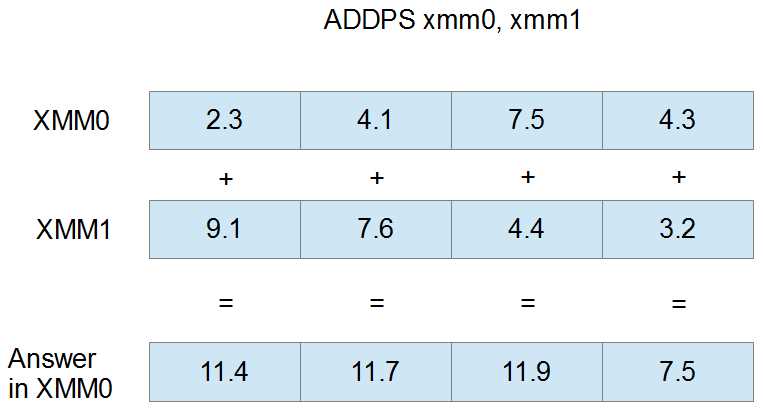
Figure 22
Subtracting Floating Point Values
Table 21
Mnemonic | Meaning | Operands | Instruction Set |
|---|---|---|---|
SUBPD | Subtract packed doubles | [xmm], [xmm/mem128] | SSE2 |
VSUBPD | Subtract packed doubles | [xmm], [xmm], [xmm/mem128] | AVX |
VSUBPD | Subtract packed doubles | [ymm], [ymm], [ymm/mem256] | AVX |
SUBPS | Subtract packed singles | [xmm], [xmm/mem128] | SSE |
VSUBPS | Subtract packed singles | [xmm], [xmm], [xmm/mem128] | AVX |
VSUBPS | Subtract packed singles | [ymm], [ymm], [ymm/mem256] | AVX |
SUBSD | Subtract scalar double | [xmm], [xmm/mem64] | SSE2 |
VSUBSD | Subtract scalar double | [xmm], [xmm], [xmm/mem64] | AVX |
SUBSS | Subtract scalar single | [xmm], [xmm/mem32] | SSE |
VSUBSS | Subtract scalar single | [xmm], [xmm], [xmm/mem32] | AVX |
The subtraction instructions subtract elements in one register or memory from the corresponding elements in another register. The two-operand versions of the instructions subtract the elements of the second operand from the corresponding elements in the first, and store the answer in the first operand. The three-operand AVX versions subtract the elements of the third operand from those in the second, and store the result in the first operand.
The following example illustrates a SUBPS instruction using XMM0 and XMM1 as operands. The four single-precision floats in XMM1 are subtracted from those in XMM0, and the result is placed into XMM0.
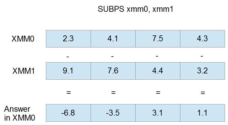
Figure 23
Dividing Floating Point Values
Table 22
Mnemonic | Meaning | Operands | Instruction Set |
|---|---|---|---|
DIVPD | Divide packed doubles | [xmm], [xmm/mem128] | SSE2 |
VDIVPD | Divide packed doubles | [xmm], [xmm], [xmm/mem128] | AVX |
VDIVPD | Divide packed doubles | [ymm], [ymm], [ymm/mem256] | AVX |
DIVPS | Divide packed singles | [xmm], [xmm/mem128] | SSE |
VDIVPS | Divide packed singles | [xmm], [xmm], [xmm/mem128] | AVX |
VDIVPS | Divide packed singles | [ymm], [ymm], [ymm/mem256] | AVX |
DIVSD | Divide scalar double | [xmm], [xmm/mem64] | SSE2 |
VDIVSD | Divide scalar double | [xmm], [xmm], [xmm/mem64] | AVX |
DIVSS | Divide scalar single | [xmm], [xmm/mem32] | SSE |
VDIVSS | Divide scalar single | [xmm], [xmm], [xmm/mem32] | AVX |
The division instructions divide elements in one register or memory by the corresponding elements in another. The two-operand versions divide the values in the first operand by the corresponding values in the second, and store the results in the first. The three-operand versions divide the elements in the second operand by those in the third and store the results in the first operand.
The sample illustration is of the DIVPD instruction with XMM0 and XMM1 as operands. The elements in XMM0 are divided by those in XMM1 and the resulting doubles are stored in XMM0.
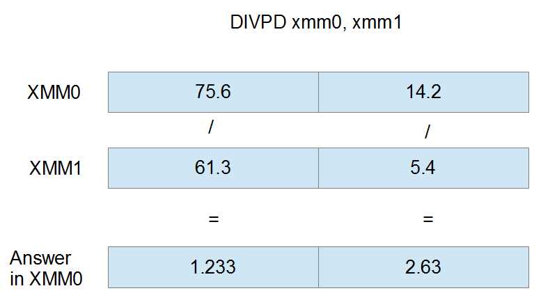
Figure 24
Multiplying Floating Point Values
Table 23
Mnemonic | Meaning | Operands | Instruction Set |
|---|---|---|---|
MULPD | Multiply packed doubles | [xmm], [xmm/mem128] | SSE2 |
VMULPD | Multiply packed doubles | [xmm], [xmm], [xmm/mem128] | AVX |
VMULPD | Multiply packed doubles | [ymm], [ymm], [ymm/mem256] | AVX |
MULPS | Multiply packed singles | [xmm], [xmm/mem128] | SSE |
VMULPS | Multiply packed singles | [xmm], [xmm], [xmm/mem128] | AVX |
VMULPS | Multiply packed singles | [ymm], [ymm], [ymm/mem256] | AVX |
MULSD | Multiply scalar double | [xmm], [xmm/mem64] | SSE2 |
VMULSD | Multiply scalar double | [xmm], [xmm], [xmm/mem64] | AVX |
MULSS | Multiply scalar single | [xmm], [xmm/mem32] | SSE |
VMULSS | Multiply scalar single | [xmm], [xmm], [xmm/mem32] | AVX |
The multiplication instructions multiply the elements in one register by the corresponding elements in another register or memory. The two-operand versions multiply the values in the first operand by those in the second and store the results in the first operand. The three-operand versions multiply the values in the third operand by those in the second, and store the results in the first operand.
The following figure is the MULPD instruction using XMM0 and XMM1 as operands. The doubles in XMM0 are multiplied by those in XMM1 and the result is stored in XMM0.
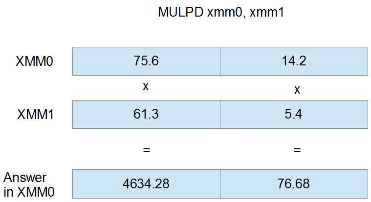
Figure 25
Square Root of Floating Point Values
Table 24
Mnemonic | Meaning | Operands | Instruction Set |
|---|---|---|---|
SQRTPD | Square root packed doubles | [xmm], [xmm/mem128] | SSE2 |
VSQRTPD | Square root packed doubles | [xmm], [xmm/mem128] | AVX |
VSQRTPD | Square root packed doubles | [ymm], [ymm/mem256] | AVX |
SQRTPS | Square root packed singles | [xmm], [xmm/mem128] | SEE |
VSQRTPS | Square root packed singles | [xmm], [xmm/mem128] | AVX |
VSQRTPS | Square root packed singles | [ymm], [ymm/mem256] | AVX |
SQRTSD | Square root scalar double | [xmm], [xmm/mem64] | SSE2 |
VSQRTSD | Square root scalar double | [xmm], [xmm/mem64] | AVX |
SQRTSS | Square root scalar single | [xmm], [xmm/mem32] | SSE |
VSQRTSS | Square root scalar single | [xmm], [xmm/mem32] | AVX |
The square root instructions calculate the square root of the elements in the second operand and store the answers in the first operand.
The following figure is the SQRTPD instruction using the registers XMM0 and XMM1 as operands. The first operand (XMM0) is ignored in the calculation; its elements have been grayed out. The final results in the elements of XMM0 are the square root of the doubles in XMM1.
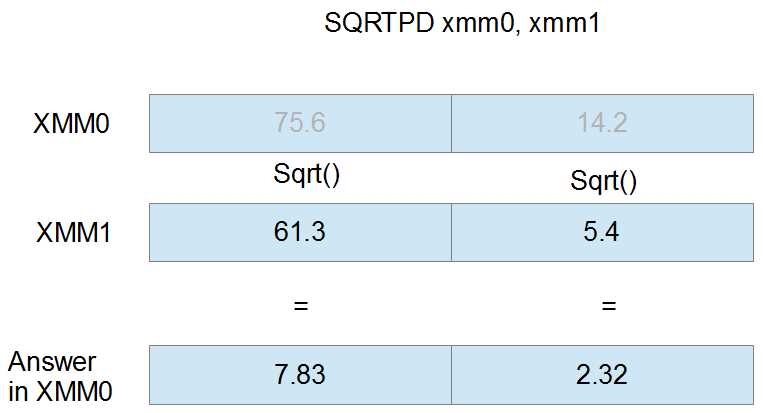
Figure 26
Reciprocal of Single-Precision Floats
Table 25
Mnemonic | Meaning | Operands | Instruction Set |
|---|---|---|---|
RCPPS | Reciprocal packed singles | [xmm], pxmm/mem128] | SSE |
VRCPPS | Reciprocal packed singles | [xmm], [xmm/mem128] | AVX |
VRCPPS | Reciprocal packed singles | [ymm], [ymm/mem128] | AVX |
RCPSS | Reciprocal scalar single | [xmm], [xmm/mem32] | SSE |
VRCPSS | Reciprocal scalar single | [xmm], [xmm/mem32] | AVX |
VRCPSS | Reciprocal scalar single | [ymm], [ymm/mem32] | AVX |
The reciprocal instructions calculate the reciprocal (1/x, where x is the element) of the elements in the second operand and store the result in the elements of the first operand. The elements of the first operand are ignored for the calculation. The result of dividing by zero in these instructions is infinity. These instructions only give a quick approximation of the real reciprocal; they are intended to be used when exact precision is not required.
The following figure shows the RCPPS instruction with XMM0 and XMM1 as operands. The initial values in XMM0 are ignored by the instruction and are overwritten by the reciprocal of the elements in XMM1. They are grayed out in Figure 27.
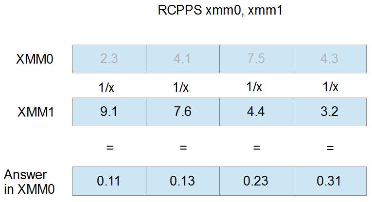
Figure 27
Reciprocal of Square Root of Single-Precision Floats
RSQRTPS [xmm], [xmm/mem128] – SSE
VRSQRTPS [xmm], [xmm/mem128] – AVX
VRSQRTPS [ymm], [ymm/mem256] – AVX
RSQRTSS [xmm], [xmm/mem32] – SSE
VRSQRTSS [xmm], [xmm], [xmm/mem32] – AVX
These instructions calculate the reciprocal of the square root (1/sqrt(x) or sqrt(x)/x, where x is the element) of the elements in the second operand and store the results in the first operand. In other words, they divide one by the square root of the elements in the second operand and store the results in the first operand. The answers are not precise and the instruction is intended for use only when a quick approximation is required.
The following figure shows the RSQRTPS instruction using XMM0 and XMM1 as operands. The values in XMM0 are ignored for the calculation and have been grayed out. The resulting reciprocal square roots are only those from the second operand.
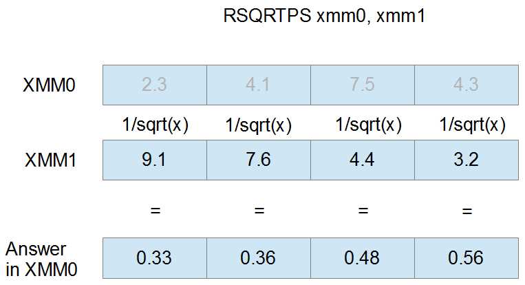
Figure 28
Boolean Operations
All of these operations essentially do exactly the same thing despite the data types in the registers, since a bitwise operation on packed doubles has the same effect on a SIMD register as a bitwise operation on packed singles. Some CPUs suffer a minor performance penalty when data in SIMD registers is not treated as the same size. For this reason, it is safest to use the bitwise or Boolean instructions designed for the particular data type you are working with.
AND NOT Packed Doubles/Singles
ANDNPD [xmm], [xmm/mem128] – SSE2
PANDN [xmm], [xmm/mem128] – SSE2
VANDNPD [xmm], [xmm], [xmm/mem128] - AVX
VANDNPD [ymm], [ymm], [ymm/mem256] – AVX
ANDNPS [xmm], [xmm/mem128] – SSE2
VANDNPS [xmm], [xmm], [xmm/mem128] – AVX
VPANDN [xmm], [xmm], [xmm/mem128] - AVX
VANDNPS [ymm], [ymm], [ymm/mem256] – AVX
The AND NOT instructions first complement an operand, then perform a bitwise AND between two operands. They store the result in the destination (see the MMX Boolean instructions for the truth table for this instruction). For the two-operand versions of these instructions, the first operand is complemented and then a bitwise AND is performed between the bits of both operands. The result is stored in the first operand.
For the three-operand versions of these instructions, the second operand is complemented and then a bitwise AND is performed between the second and third operands. The result is stored in the first operand.
This instruction is useful for creating bit masks that represent negative comparisons.
AND Packed Doubles/Singles
ANDPD [xmm], [xmm/mem128] – SSE2
PAND [xmm], [xmm/mem128] – SSE2
VANDPD [xmm], [xmm], [xmm/mem128] - AVX
VPAND [xmm], [xmm], [xmm/mem128] - AVX
VANDPD [ymm], [ymm], [ymm/mem256] – AVX
ANDPS [xmm], [xmm/mem128] – SSE
VANDPS [xmm], [xmm], [xmm/mem128] - AVX
VANDPS [ymm], [ymm], [ymm/mem256] – AVX
These instructions perform a bitwise AND between two operands. The two-operand versions of this instruction perform a bitwise AND between the first and second operands, storing the result in the first operand. The three-operand versions perform a bitwise AND between the second and third operand and store the results in the first operand.
OR Packed Doubles/Singles
ORPD [xmm], [xmm/mem128] – SSE2
POR [xmm], [xmm/mem128] – SSE2
VORPD [xmm], [xmm], [xmm/mem128] - AVX
VPOR [xmm], [xmm], [xmm/mem128] – AVX
VORPD [ymm], [ymm], [ymm/mem256] – AVX
ORPS [xmm], [xmm/mem128] – SSE
VORPS [xmm], [xmm], [xmm/mem128] - AVX
VORPS [ymm], [ymm], [ymm/mem256] – AVX
The OR instructions perform a bitwise OR between two operands. The two-operand versions perform a bitwise OR between the first and second operand and store the results in the first operand. The three-operand AVX versions perform a bitwise OR between the second and third operands, storing the results in the first operand.
XOR Packed Doubles/Singles
XORPD [xmm], [xmm/mem128] – SSE2
PXOR [xmm], [xmm/mem128] – SSE2
VXORPD [xmm], [xmm], [xmm/mem128] - AVX
VXORPD [ymm], [ymm], [ymm/mem256] – AVX
VPXOR [xmm], [xmm], [xmm/mem128] – AVX
XORPS [xmm], [xmm/mem128] – SSE
VXORPS [xmm], [xmm], [xmm/mem128] - AVX
VXORPS [ymm], [ymm], [ymm/mem256] – AVX
The XOR instructions perform a bitwise XOR operation between two operands. The two-operand versions of these instructions perform a bitwise XOR between the first and second operands and store the results in the first operand. The three-operand versions perform a bitwise XOR between the second and third operands and store the result in the first operand.
Comparison Instructions
Comparing Packed Doubles and Singles
CMPxxPtt [xmm], [xmm/mem128] - SSE and SSE2 versions
VCMPxxPtt [xmm], [xmm], [xmm/mem128] - AVX versions
VCMPxxPtt [ymm], [ymm], [ymm/mem256] - AVX versions
There are many comparison instructions; the mnemonics follow the outline (CMPxxPtt or VCMPxxPtt) where the xx is replaced by the operator abbreviation (from the Comparison Operators table that follows) and the tt is replaced by the data type (D for packed double-precision floats and S for packed single-precision floats).
Table 26: Comparison Operators
Abbreviation | Meaning |
|---|---|
EQ | Equal to |
LT | Less than |
LE | Less than or equal to |
UNORD | Unordered (NaN or Undefined) |
ORD | Ordered (not NaN or Undefined) |
NEQ | Not equal to |
NLT | Greater than or equal to, not less than |
NLE | Greater than, not less or equal to |
They perform the comparison operator between corresponding elements of two operands. All bits of any elements that the operator is true are set to 1. All bits of any elements where the operator is false are set to 0.
In the SSE and SSE2 versions, the comparison is performed between operands one and two and the resulting bit masks are stored in the first operand.
In the AVX versions, the comparison is performed between operands two and three, and the resulting bit masks are placed into the first operand.
The UNORD and ORD comparison operators are used to determine where various NaN (not a number) elements are. NaN values in doubles or floats are unordered and will return true if the UNORD comparison is used and false if ORD is used. All numerically orderable values (those that are not NaN or #IND) return true when the ORD operator is used and false when the UNORD operator is used.
Comparing Scalar Doubles and Singles
CMPxxStt [xmm], [xmm/mem64/mem32] - SSE and SSE2 versions
VCMPxxStt [xmm], [xmm], [xmm/mem64/mem32] - AVX versions
The scalar versions of the comparison instructions are the same as their packed counterparts, only they perform the comparison on the lowest double or single. They have an S for scalar in their mnemonic instead of the P for packed.
Comparing and Setting rFlags
COMISD [xmm], [xmm/mem64] - SSE2
VCOMISD [xmm], [xmm/mem64] - AVX
COMISS [xmm], [xmm/mem32] - SSE
VCOMISS [xmm], [xmm/mem32] – AVX
These interesting instructions bridge the gap between the SIMD instruction sets and the regular x86 instruction sets by comparing SSE or AVX registers, but setting the rFlags register. The instructions are scalar, and compare either the lowest single-precision floats (COMISS and VCOMISS) or the lowest doubles (COMISD and VCOMISD). They set the flags register in the following manner:
Table 27: x86 Flags after xCOMISxx
Condition | Zero Flag | Parity Flag | Carry Flag |
NaN | 1 | 1 | 1 |
Parameter 1 > Parameter 2 | 0 | 0 | 0 |
Parameter 1 < Parameter 2 | 0 | 0 | 1 |
Parameter 1 = Parameter 2 | 1 | 0 | 0 |
Converting Data Types/Casting
Conversion Instructions
Converting to Doubles
CVTDQ2PD [xmm], [xmm/mem64] ; Converts two dwords to doubles using SSE2
VCVTDQ2PD [xmm], [xmm/mem64] ; Converts two dwords to doubles using AVX
VCVTDQ2PD [ymm], [ymm/mem128] ; Converts two dwords to doubles using AVX
CVTPS2PD [xmm], [xmm/mem64] ; Converts packed singles to packed doubles using SSE2
VCVTPS2PD [xmm], [xmm/mem64] ; Converts packed singles to packed doubles using AVX
VCVTPS2PD [ymm], [ymm/mem128] ; Converts packed singles to packed doubles using AVX
CVTSI2SD [xmm], [reg32/64] ; Converts from x86 register to double using SSE2
VCVTSI2SD [ymm], [ymm], [reg32/64] ; Converts from x86 register to double using AVX
CVTSS2SD [xmm], [xmm/mem64] ; Converts a scalar single to a scalar double using SSE2
VCVTSS2SD [ymm], [ymm], [ymm/mem64] ; Converts a scalar single to a scalar double using AVX
Converting to Singles
CVTDQ2PS [xmm], [xmm/mem128] ; Converts packed dwords to singles using SSE2
VCVTDQ2PS [xmm], [xmm/mem128] ; Converts packed dwords to singles using AVX
VCVTDQ2PS [ymm], [ymm/mem256] ; Converts packed dwords to singles using AVX
CVTPD2PS [xmm], [xmm/mem128] ; Converts packed doubles to singles using SSE2
VCVTPD2PS [xmm], [xmm/mem128] ; Converts packed doubles to singles using AVX
VCVTPD2PS [ymm], [ymm/mem256] ; Converts packed doubles to singles using AVX
CVTSD2SS [xmm], [xmm/mem64] ; Converts scalar double to scalar single using SSE2
VCVTSD2SS [ymm], [ymm], [ymm/mem64] ; Converts scalar double to scalar single using AVX
CVTSI2SS [xmm], [reg32/64] ; Converts from x86 registers to a scalar single using SSE2
VCVTSI2SS [ymm], [ymm], [reg32/64] ; Converts from x86 registers to a scalar single using AVX
Converting to Integers
CVT(T)PD2DQ [xmm], [xmm/mem128] ; Converts packed doubles to dwords using SSE2
VCVT(T)PD2DQ [xmm], [xmm/mem128] ; Converts packed doubles to dwords using AVX
VCVT(T)PD2DQ [ymm], [ymm/mem256] ; Converts packed doubles to dwords using AVX
CVT(T)PS2DQ [xmm], [xmm/mem128] ; Converts singles to dwords using SSE2
VCVT(T)PS2DQ [xmm], [xmm/mem128] ; Converts singles to dwords using AVX
VCVT(T)PS2DQ [ymm], [ymm/mem256] ; Converts singles to dwords using AVX
CVT(T)SD2SI [reg32/64], [xmm/mem32/64] ; Converts double to x86 register using SSE2
VCVT(T)SD2SI [reg32/64], [ymm/mem32/64] ; Converts double to x86 register using AVX
CVT(T)SS2SI [reg32/64], [mem32/64] ; Converts scalar single to scalar integer using SSE2
VCVT(T)SS2SI [reg32/64], [mem32/64] ; Converts scalar single to scalar integer using AVX
The data conversion instructions convert between doubles, singles, and integer data. They convert the elements (or element) in the second operand to some other data type and store the converted results in the elements of the first operand. The conversion is analogous to a C++ type cast.
The versions that convert floating point values to x86 registers only work on scalar values, since the x86 registers are essentially scalar in nature. They are useful because they allow answers calculated using SSE floating point to be quickly and easily cast to integers in the x86 registers.
When converting to integers, you have the option of either using truncation (by placing the additional T in the middle of the mnemonic, indicated in the previous list by the (T)) or using the rounding function specified in the MXCSR register.
Selecting the Rounding Function
STMXCSR [mem32] – Store MXCSR
LDMXCSR [mem32] – Load MXCSR
The conversion instructions that convert from a floating point value to an integer perform rounding based on the rounding function (bits 13 and 14) of the MXCSR register.
Table 28: Rounding Function Bits in MXCSR
Bit 14 | Bit 13 | Rounding Function |
|---|---|---|
0 | 0 | Round to nearest integer |
0 | 1 | Round down to nearest integer |
1 | 0 | Round up to nearest integer |
1 | 1 | Truncate (round toward 0) |
To set the rounding function in MXCSR, the register must first be copied to RAM using the store MXCSR instruction, STMCXSR. Then bits 13 and 14 can be set in RAM using the bit test instructions, BTS and BTR (or the Boolean instructions). Finally, this altered value of MXCSR can be loaded from RAM back into the real MXCSR using the load MXCSR instruction, LDMXCSR.
The LDMXCSR and STMCXSR instructions both take a single 32-bit memory operand. In STMXCSR, this operand is a variable to store the MXCSR in RAM. In LDMXCSR, the operand is the memory location from which to copy the new values of the MXCSR.
; Example of selecting Round to Nearest, 00 STMXCSR mxcsrState ; Copy MXCSR to the 32-bit memory operand btr mxcsrState, 13 ; Unset both bits, set it to 0 btr mxcsrState, 14 LDMXCSR mxcsrState ; Load the altered value back into MXCSR ; Example of selecting Round Down, 01 STMXCSR mxcsrState ; Copy MXCSR to the 32-bit memory operand bts mxcsrState, 13 ; Set bit 13 to 1 btr mxcsrState, 14 ; And bit 14 to 0 LDMXCSR mxcsrState ; Load the altered value back into MXCSR |
- 1800+ high-performance UI components.
- Includes popular controls such as Grid, Chart, Scheduler, and more.
- 24x5 unlimited support by developers.