
Assembly Language Succinctly®

CHAPTER 3
Memory Spaces
Computers are made of many components, some of which have memory or spaces to store information. The speed of these various memory spaces and the amount of memory each is capable of holding are quite different. Generally, the closer to the CPU the memory space, the faster the data can be read and written.
There are countless possible memory spaces inside a computer: the graphics card, USB sticks, and even printers and other external devices all add memory spaces to the system. Usually the memory of a peripheral device is accessed by the drivers that come with the devices. The following table lists just a few standard memory spaces.
Table 3: Memory Spaces
Memory Space | Speed | Capacity |
Human input | Unknown | Unknown |
Hard drives and external storage | Extremely slow | Massive, > 100 gigabytes |
RAM | Fast | Large, gigabytes |
CPU caches | Very fast | Small, megabytes |
CPU registers | Fastest | Tiny, < 1 kilobyte |
The two most important memory spaces to an assembly program are the RAM and the CPU memories. RAM is the system memory; it is large and quite fast. In the 32-bit days, RAM was segmented, but nowadays we use a flat memory model where the entire system RAM is one massive array of bytes. RAM is fairly close to the CPU, as there are special buses designed to traffic data to and from the RAM hundreds of times quicker than a hard drive.
There are small areas of memory on the CPU. These include the caches, which store copies of data read from external RAM so that it can be quickly accessed if required. There are usually different levels of cache on a modern CPU, perhaps up to 3. Level 1 (abbreviated to L1 cache) is the smallest but quickest, and level 3 (abbreviated to L3 cache) is the slowest cache but may be megabytes in size. The operation of the caches is almost entirely automatic. The CPU handles its own caches based on the data coming into it and being written to RAM, but there are a few instructions that deal specifically with how data should or should not be cached.
It is important to be aware of the caches, even though in x86 programmers are not granted direct control over them. When some value from an address in RAM is already in the L1 cache, reading or writing to it is almost as fast as reading and writing to the registers. Generally, if data is read or written, the CPU will expect two things:
- The same data will probably be required again in the near future (temporal locality).
- The neighboring data will probably also be required (spatial locality).
As a result of these two expectations, the CPU will store both the values requested by an instruction from RAM and its cache. It will also fetch and store the neighboring values.
More important than the CPU caches are the registers. The CPU cannot perform calculations on data in RAM; data must be loaded to the CPU before it can be used. Once loaded from RAM, the data is stored in the CPU registers. These registers are the fastest memory in the entire computer. They are not just close to the CPU, they are the CPU. The registers are just a handful of variables that reside on the CPU, and they have some very strange characteristics.
Registers
The registers are variables residing on the CPU. The registers have no data type. Specifically, they are all data types, bytes, words, dwords, and qwords. They have no address because they do not reside in RAM. They cannot be accessed by pointers or dereferenced like data segment variables.
The present register set (x64) comes from earlier x86 CPUs. It is easiest to understand why you have these registers when you examine the older CPU register sets. This small trip through history is not just for general knowledge, as most of the registers from 1970s CPUs are still with us.
Note: There is no actual definition for what makes a CPU 64-bit, 32-bit, or 16-bit, but one of the main defining characteristics is the size of the general purpose registers. x64 CPUs have 16 general purpose registers and they are all 64 bits wide.
16-Bit Register Set

Figure 12
Let us begin by examining the original 16-bit 8086 register set from the 1970s. Each of the original 8086 registers had a name indicating what the register was mainly used for. The first important thing to note is that AX, BX, CX, and DX can each be used as a single 16-bit register or as two 8-bit registers.
AX, BX, CX, and DX: The register AL (which means A Low) is the low byte of AX, and the register AH (which means A High) is the upper byte. The same is true for BX, CX, and DX; each 16-bit register has two 8-bit versions. This means that changing one of the low bytes (AL, BL, CL, or DL) will change the value in the word-sized version (AX, BX, CX, or DX). The same is true of changing the high bytes (AH, BH, CH, and DH). This also means that programmers can perform arithmetic on bytes or words. The four 16-bit registers can be used as eight 8-bit registers, four 16-bit registers, or any other combination.
SI and DI: These are the source and destination index registers. They are used for string instructions where SI points to the source of the instruction and DI points to the destination. They were originally only available in 16-bit versions, but there were no byte versions of these registers like there are for AX, BX, CX, and DX.
BP: This is the base pointer; it is used in conjunction with the SP to assist in maintaining a stack frame when calling procedures.
SP: This is the stack pointer; it points to the address of the first item that will be popped from the stack upon executing the POP instructions.
IP: This is the instruction pointer (called PC for Program Counter in some assembly languages); it points to the spot in RAM that is to be read for the next machine code bytes. The IP register is not a general purpose register, and IP cannot be referenced in instructions that allow the general purpose registers as parameters. Instead, the IP is manipulated implicitly by calling the jump instructions (JMP, JE, JL, etc.). Usually the IP simply counts up one instruction at a time. As the code is executed, instructions are fetched from RAM at the address the IP indicates, and they are fed into the CPU's arithmetic units and executed. Jumping instructions and procedure calls cause the IP to move to some other spot in RAM and continue reading code from the new address.
Flags: This is another special register; it cannot be referenced as a general purpose register. It holds information about various aspects of the state of the CPU. It is used to perform conditional statements, such as jumps and conditional moves. The flags register is a set of 16 bits that each tell something about the recent events that have occurred in the CPU. Many arithmetic and compare instructions set the bits in the flags register, and with subsequent conditional jumps and moves performs the instructions based on the status of the bits of this register. There are many more flag bits in the flags register, but the following table lists the important ones for general application programming.
Table 4: Flags Register
Flag Name | Bit | Abbrev. | Description |
|---|---|---|---|
Carry | 0 | CF | Last arithmetic instruction resulted in carry or borrow. |
Parity | 2 | PF | 1 if lowest byte of last operation has even 1 count. |
Auxiliary Carry | 4 | AF | Carry for BCD (not used any more). |
Zero | 6 | ZF | Last result equaled zero. |
Sign | 7 | SF | Sign of last operation, 1 for – and 0 for +. |
Direction | 10 | DF | Direction for string operations to proceed. |
Overflow | 11 | OF | Carry flag for signed operations. |
The individual flag bits of the flags register are not only used for what they were originally named. The names of the flags also reflect the most general use for each. For instance, CF is used to indicate whether the last addition or subtraction resulted in a final carry or borrow, but it is also set by the rotating instructions.
The parity flag was originally used in error checking, but it is now almost completely useless. It is set based on the count of bits set to 1 in the lowest byte of the last operation's result. If there is an even number of 1 bits set by the last result, the parity flag will be set to 1. If not, it will be cleared to 0. The auxiliary carry flag was used in Binary Coded Decimal (BCD) operations, but most of the BCD instructions are no longer available in x64.
The final four registers in the 8086 list (SS, CS, DS, and ES) are the segment pointers. They were used to point to segments in RAM. A 16-bit pointer can point to at most 64 kilobytes of different RAM addresses. Some systems at the time had more than 64 kilobytes of RAM. In order to access more than this 64-KB limit, RAM was segmented and the segment pointers specified a segment of the total installed RAM, while another pointer register held a 16-bit offset into the segment. In this way, a segment pointer in conjunction with an offset pointer could be thought of as a single 32-bit pointer. This is a simplification, but we no longer use segmented memory.
32-Bit Register Set
When 32-bit CPUs came about, backwards compatibility was a driving force in the register set. All previous registers were kept but were also extended to allow for 32-bit operations.
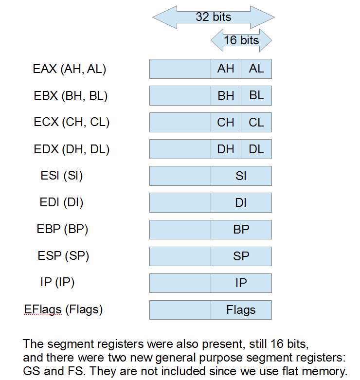
Figure 13
The original registers can all still be referenced as the low 16 bits of the new 32-bit versions. For example, AX is the lowest word of EAX, and AL is still the lowest byte of AX, while AH is the upper byte of AX. The same is true for EBX, ECX, and EDX. As a result of this expansion to the register set, the 386 and 486 CPUs could perform arithmetic on bytes, words, and dwords.
The SI, DI, BP, and SP registers also added a 32-bit version and the original 16-bit registers were the low word of this. There was no byte form of these registers at that point.
The segment registers were also present and another two were added (GS and FS). Again, the segment registers are no longer as useful as they were, since modern Windows systems use a flat memory model.
Note: It is perfectly acceptable to use the different parts of a single register as two different operands to an instruction. For instance, “mov al, ah” moves the data from AH to AL. This is possible because the CPU has internal temporary registers to which it copies the values prior to performing arithmetic.
64-bit Register Set
Finally, we arrive at our present register set. This was a massive change, but once again, almost all backwards compatibility was maintained. In addition to increasing all general purpose registers to 64 bits wide by adding another 32 bits to the left of the 32-bit versions (EAX, EBX, etc.), eight new general purpose registers were added (R8 to R15). BP, SP, DI, and SI could also now have their lowest bytes referenced, as well as the lowest word or lowest dword.
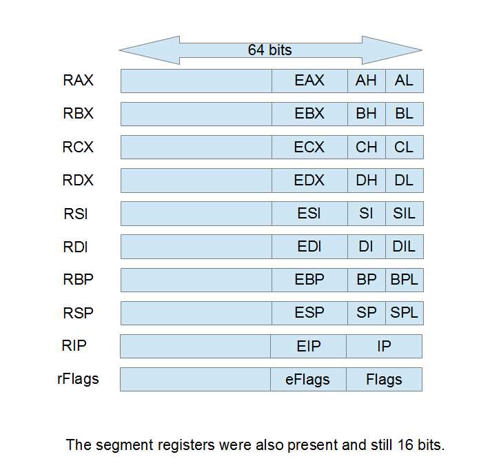
Figure 14
The general purpose registers AX, BX, CX, and DX still have high bytes (AH, BH, CH, and DH), but none of the other registers have their second byte addressable (there is no RDH, a high byte version of RDI). The high bytes of RAX, RBX, RCX, or RDX cannot be used with the low bytes of the other registers in a single instruction. For example, mov al, r8b is legal, but mov ah, r8b is not.
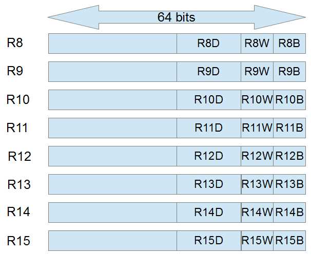
Figure 15
These are the new 64-bit general purpose registers R8 to R15. They can be used for anything the original RAX, RBX, RCX, or RDX registers can be used for. It is not clear in the diagram, but the lowest 32 bits of the new registers are addressable as R8D. The lowest 16 bits of R8 are called R8W and the lowest byte is called R8B. Although the image seems to depict R8D adjacent to R8W and R8B, R8W is actually the low 16 bits, exactly the same as RAX, EAX, AX, and AL.
- 1800+ high-performance UI components.
- Includes popular controls such as Grid, Chart, Scheduler, and more.
- 24x5 unlimited support by developers.