
Arduino Succinctly®

CHAPTER 3
Working with Buttons
Every now and then, you will want to interact with the user. The most common element for interacting with the user is a button. The most common type of button used in electronics nowadays is the push button. This button is not closing the circuit constantly but only for as long as it is pressed. The most basic example of using the pushbutton is turning the LED on when the button is pressed. I will describe this in the next section.
Pushbutton
This example is the Hello World when working with buttons. Basically what it does is it turns the LED on when a button is pressed and then turns it off once the button is released. Here is the parts list and the wiring:
Parts list for this section:
- Arduino Uno
- Pushbutton
- USB cable
- 1x 100-Ohms resistor for the LED (pin 13)
- 1x 10k Ohm resistor for the Pushbutton
- Breadboard
- 1x 5mm LED
- 5x Breadboard jumper wire
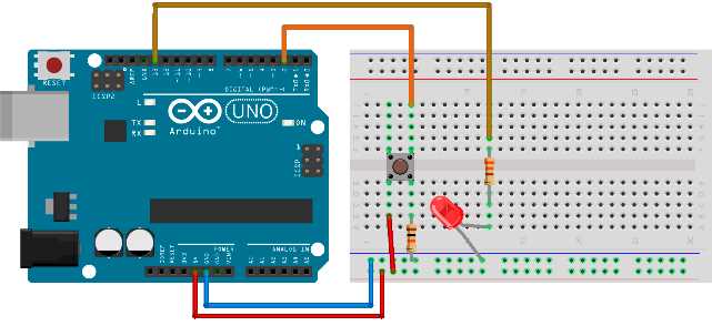
Figure 26: Pushbutton wiring schema
The code for the example is pretty straightforward. We are constantly reading the state from pin 2 and, if it’s in a high state, we turn the LED on. Note that we connected the LED to pin 13 so that the onboard LED will shine too. Here’s the code:
// variable holding button state int buttonState = 0; // LED pin int ledPin = 13; // Button pin int buttonPin = 2; void setup() { // initialize pins pinMode(ledPin, OUTPUT); pinMode(buttonPin, INPUT); } void loop(){ // read the state of the button buttonState = digitalRead(buttonPin);
// pressed button is in state high if (buttonState == HIGH) { // LED on digitalWrite(ledPin, HIGH); } else { // LED off digitalWrite(ledPin, LOW); } } |
In this example, we will read the pin input for the first time. We are doing it with the digitalRead function. The loop that checks the reading is a lot faster than the human eye can notice, so we are not noticing an interesting effect with the button. We see the LED immediately on and can’t perceive any oscillations while the button is initially pressed. Also, we don’t see that the LED is blinking for a while after we release the button. Let’s look at the next example and go deeper into this interesting effect.
Quirky Pushbutton
The wiring and the parts for this section are the same as in the previous one (so please have a look at those schematics). The difference is in the programming and in the use. For instance, turning the LED on and off is not the most useful case when working with buttons. When microcontrollers are involved, it’s usually some sort of a state change. So we will change the LED state when we press the button. To do this, we will use the following code:
// variable holding button state int buttonState; // variable holding previous button state int previousButtonState = LOW; // variable holding the LED state int ledState = HIGH; // LED pin int ledPin = 13; // Button pin int buttonPin = 2; void setup() { // initialize pins pinMode(ledPin, OUTPUT); pinMode(buttonPin, INPUT); } void loop(){ // read the state of the button int reading = digitalRead(buttonPin);
// if the button is pressed, change the state if (reading != buttonState) { buttonState = reading;
// toggle the LED state only when the button is pushed if (buttonState == HIGH) { ledState = !ledState; } }
// turn the LED on or off depending on the state digitalWrite(ledPin, ledState);
// save current reading so that we can compare in the next loop previousButtonState = reading; } |
Now, try to play with this button for a while. If you do so, you will notice that it’s not behaving as you would expect; it sometimes misses the button press, behaving a bit quirky. You will notice the light remains on even when it shouldn’t and vice versa. Although we have a digitalRead function, there is an interesting analog effect at work here.
The switch is made of metal parts and the button press brings them together. There is a movement associated with this action, and the metal surfaces inside the switch bounce away and then come back together again a couple of times (within a very short period of time). This is a known effect and it does not represent a problem when, for instance, turning a light bulb on and off. It didn’t represent a problem in our first example with the button where the LED was on for as long as the button is pressed. But, when it comes down to logical circuits where we can read the changes really fast during a short period of time, we will not be sure if the button was pressed or not.
Let’s look at the following picture. Essentially, every change in the spike will cause the LED state to change. So, using this button without some kind of noise filtering is pretty much playing a lottery. And you won’t be sure if the LED is going to turn on or off when you release or press the button. Here’s a figure showing what’s going on with the electrical current during a short button press. Remember, every change in the spike is a change in the state of the LED:
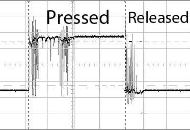
Figure 27: Electricity reading during a short button press, followed by a release
The human eye won’t perceive every single change but we will notice faulty state changes at the end of a button press. In the next section, we will implement a filtering technique to avoid the quirky behavior. The circuit and the parts will remain the same as in this section.
Pushbutton with Noise Filtering Software
The parts list and the wiring are the same for this as they were in the previous example. The difference is in the software that filters the pushbutton noise:
// variable holding the button state int buttonState; // variable holding previous button state int previousButtonState = LOW; // variable holding the LED state int ledState = HIGH; int buttonPin = 2; const int ledPin = 13; // millis always stored in long // becomes too big for int after 32,767 millis or around 32 seconds // timestamp of a previous bounce long previousDebounceTime = 0; // debounce time in millis, if the LED is still quirky increase this value long debounceDelay = 50; void setup() { pinMode(buttonPin, INPUT); pinMode(ledPin, OUTPUT); } void loop() { // for now it's the same as in previous example int reading = digitalRead(buttonPin);
// if the previous reading is different than the previous button state if (reading != previousButtonState) { // we'lll reset the debounce timer previousDebounceTime = millis(); }
// if the reading is the same over a period of debounceDelay if ((millis() - previousDebounceTime) > debounceDelay) { // check if the button state is changed if (reading != buttonState) { buttonState = reading;
// toggle the LED state only when the button is pushed if (buttonState == HIGH) { ledState = !ledState; } } }
// set the LED: digitalWrite(ledPin, ledState);
// save current reading so that we can compare in the next loop previousButtonState = reading; } |
Now, to some people, the code listing might seem as a bit too complicated, and that’s perfectly understandable. There is a neat hardware trick that we can use to filter out the noise. We can use an electronic component called a capacitor.
Pushbutton with Noise-Filtering Hardware
We will now use almost the same components and wiring as we did with the quirky and basic pushbutton example. To filter out the noise, we will add a capacitor to the circuit.
Parts list for this section:
- Arduino Uno
- Pushbutton
- USB cable
- 1x 100-Ohms resistor for the LED
- 1x 10k-Ohm resistor for the pushbutton
- Breadboard
- 1x 5mm LED
- 5x Breadboard jumper wire
- 10uF Capacitor
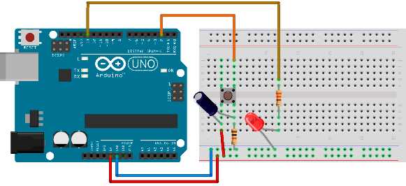
Figure 28: Pushbutton with capacitor filtering out the noise
The programming is the same as with the quirky pushbutton. The noise-filtering assignment is left to the capacitor. The capacitor has an interesting feature where it lets the current through for as long as it doesn’t get filled with electricity. When it gets filled, the current doesn’t flow through it anymore. But, if some fluctuation starts to happen, it immediately starts to release the accumulated current out of it (and basically smoothens the signals out). Actually filtering the electrical noise is one of the main usages of capacitors. There are various types and sizes of capacitors. Here are some of the basic capacitor forms:
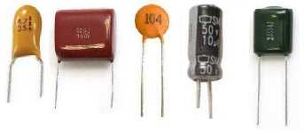
Figure 29: Basic capacitor forms
There are types of capacitors for which it’s not important how they are wired. For some, you have to be careful when connecting the positive and the negative pin. On capacitors, the positive pin is marked with a plus sign and a negative pin is marked with a “0” sign. So there are no tricks for finding out the pin polarity like there are with the LEDs. There are also some types of capacitors that have a longer leg, and that leg is the plus pin; it’s the same rule as with the LEDs. But a positive or a negative pin on a capacitor needs to have a clear marking on it.
In this section, I covered the button components and how they are used in a combination with the Arduino. I also demonstrated some of the less-known quirkiness of the buttons and how to deal with it on both the software and hardware levels. In the next section, I will show you how to use the Arduino to produce sound signals.
- 1800+ high-performance UI components.
- Includes popular controls such as Grid, Chart, Scheduler, and more.
- 24x5 unlimited support by developers.