
Arduino Succinctly®

CHAPTER 4
Using Buzzers
Giving visual feedback was always important in electronics. But there are some cases in which the light simply doesn’t cut it. A buzzer can be heard even if it’s behind the corner or there is an obstacle in between. We humans take audio signals seriously because relatively weak audio signals can even wake a person up from a deep sleep without any problem. It is also said that patients in a deep coma can still hear us clearly. So this sense is definitely important when it comes to electronics.
Audio systems are a chapter of its own and I won’t deal with them here. In this example, I’ll use relatively inexpensive components called buzzers. This component has been around for decades and it’s used mostly for notifying users. By using buzzers, electronics can notify us on some events without us having to constantly watch over some things (like popping popcorn in the microwave, waiting for a customer to enter a store, signaling the end of a game, reminding us that our favorite show is on soon, or simply waking us up).
In this chapter, I’ll go through the possible use cases for buzzers. When working with buzzers, please check if it’s alright with other people nearby, because buzzers can get really annoying sometimes. Don’t abuse the buzzers in your electronic projects, and always have in mind that they can annoy living beings. In short, notify the user with buzzers only when there is something important going on.
Counting Seconds
This is more of a Hello World example when it comes to buzzers. The end result of this example will be something like a clock ticking. Use cases are perhaps a bit limited to measuring a heartbeat, observing a phenomenon, or waiting the right amount of seconds to pass in a short period of time (like, for instance, when blanching veggies). Just imagine all the moments in which you were counting “one Mississippi, two Mississippi” and so on. This is a device that helps you count the seconds.
The most important component in this example is the buzzer. There are many versions available; the one used in this example is depicted in the following picture. But the wiring is pretty much the same regardless of how the buzzer looks like—only two pins are used. The middle pin on this buzzer is left unconnected, like this:

Figure 30: A buzzer
Parts list for this section:
- Arduino Uno
- USB cable
- 1x 100-Ohms resistor for the buzzer
- Breadboard.
- 3x Breadboard jumper wire
- Arduino-compatible passive buzzer
We will start this example with the code. It’s similar to the one that we used to make the LEDs blink. The only part that’s a bit different is that we’ll have to do some math. The pulse for making the sound is rather short and we will make it last just 10 milliseconds long. That’s about the right amount of time to perceive a short tick. The duration of this tick has to be taken into account in our loop because, after a while, we would get a significant time drift if we wait for the next cycle for a whole second, without compensating for the duration of the tick.
We would get a drift of around one second per 100 seconds. So the delay in the loop is going to be 990 milliseconds. In the setup function, we will register a pin for output and then send short pulses to the pin. After we set up the hardware, it’s going to sound something like the old clocks did. Here’s the programming part:
// We'll use pin 12 for buzzing int buzzPin = 12; void setup() { // register the pin for output pinMode(buzzPin, OUTPUT); } void loop() { // during ten milliseconds we'll make a tick digitalWrite(buzzPin, HIGH); delay(10);
// then we'll wait 990 millis to tick again digitalWrite(buzzPin, LOW); delay(990); } |
The buzzer can be a little tricky when wiring. It once happened to me that I wired the buzzer the wrong way so I heard a constant sound. When I touched the buzzer, it was extremely hot. So, after you wire the buzzer, check the buzzer to see if it’s hot. It could save you the money for the buzzer because, if you don’t check it, it could burn out. The good news is that the positive and the negative pin on the buzzer are usually very well marked so you won’t have any problems identifying the pins. If your buzzer has more than two pins, it’s just fine that one pin on the buzzer is not connected with the buzzer used (in the example, it’s the middle one). Here’s the wiring for the example:

Figure 31: Buzzer counting seconds wiring
All of the wirings to come will be similar to this one. A buzzer’s internal resistance is different from one buzzer to another, so you’ll have to use the buzzer’s data sheet to find the resistance of the buzzer (and then perhaps do some calculations to get the right resistor). In most cases, the 100-Ohm resistor is fine. To calculate the resistor rating, use the data sheet and simply divide five volts by the current rating of your element. If the current rating is 20 mA, then divide five by 0.020 A. This is just an example for you to get the overview of the whole resistor-rating determining process. Also, note that this will give you the overall resistance and you will have to subtract the buzzer’s internal resistance from this number. The calculation process is summed up in this note:
Note: Resistor = (5V / Buzzer_current_rating A) – Buzzer_internal_resistance
If you are not sure, the 100-Ohm resistor will cover you in most cases. Arduino is also built so that it’s relatively hard to damage it with the most common wiring mistakes because the pins have internal pull-up resistors that limit the current that one pin can draw. I do not consider myself or Syncfusion responsible in any way if you did the following. I connected the buzzer without the resistors and it seemed to work without any problems. Keep in mind that this is a practice with which I do not agree. I did it out of curiosity and to show you that Arduino will cover some of the beginner’s mistakes. Now some of you might play around with the buzzer and change the values of the previous program. Let’s look at the following code and try to determine what it will do with the buzzer:
// what do you think this will do? // we'll use pin 12 for buzzing int buzzPin = 12; void setup() { // register the pin for output pinMode(buzzPin, OUTPUT); } void loop() { // we'll keep the pin high for 990 ms digitalWrite(buzzPin, HIGH); delay(990);
// and then we'll make just a short break digitalWrite(buzzPin, LOW); delay(10); } |
After running the previous listing, you might be wondering what’s going on, and if you somehow typed in the previous example. Don’t worry, the example is just fine. Both examples do absolutely the same thing. We have to go a bit into the inner workings of a buzzer to explain what is actually going on here. As a short introduction, I will mention that the sound is actually a vibration traveling through a medium like air or water. And, if you look closely, you will notice that we didn’t produce any pulsating currents in the previous example. We are just outputting a current with a constant level on the pin. And what we hear as a tick is a short burst at the beginning of the pulse where the current raises from zero to the HIGH value on the pin. We’ll go a bit into this in the following section.
Changing Buzzer’s Frequency
This section uses completely the same wiring as the previous section does. We’ll just change the code as we go along to demonstrate how to change the frequency of a tone generated by the buzzer. Let’s go back to the basic principles of a loudspeaker.
A loudspeaker works by vibrating and then pushing the air around, thus causing vibrations that we can hear. There are many loudspeaker designs out there, so I won’t go into every single one of them, but I will explain the most basic one instead. In the basic form, a loudspeaker includes a magnet, a vibrating surface, and a coil.
The current goes through the coil and causes the movement of the magnet. If the current starts to alternate, the vibrating surface starts to move back and forth. This then causes the vibration of the air and forms a sound wave. This is the basic functioning principle behind a loudspeaker. Note that, in some speaker designs, the coil is put on the vibrating surface because it is much lighter than the magnet. Actually, this is how most of the speakers are built, but this is an educational example. Here it is depicted with the basic parts:
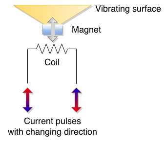
Figure 32: Basic functioning of a loudspeaker
In our previous examples, we didn’t send any specific alternating currents to the speaker. We just wrote the HIGH value to the pin and then waited while there was a constant current flowing through the pin. There was a constant flow of current; it attracted or repelled the vibrating surface just when it started to flow and then the speaker stabilized. This happened fast and, since there is a mechanical movement involved, it doesn’t stop right away. So we heard the vibrations done by the inertia of the vibrating surface. Once per second, we changed the direction of the current and this repeated so we heard a beat. So, yes, in effect, the previous examples were not using the buzzers the way they were supposed to be used. Let’s alternate the high and low really fast. Remember, this might annoy the people around you:
// we'll use pin 12 int buzzPin = 12; void setup() { // register the pin for output pinMode(buzzPin, OUTPUT); } void loop() { // high for a short while digitalWrite(buzzPin, HIGH); delay(1);
// low for a short while digitalWrite(buzzPin, LOW); delay(1); } |
Now that sounds like something. It’s better than the previous ticks; this actually sounds like a tone. Let’s have a look at the current:
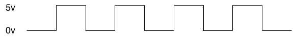
Figure 33: Voltage levels in the previous programming example
Within two milliseconds, we’ll go from high to low. We can do that 500 times per second so, in effect, the previous example produces a 500-Hz tone. If you look up the specifications of your buzzer, you might find that it supports frequencies of up to 2,500 Hz or even more. The 500-Hz tone is about as far as we can go with the milliseconds delay. The Arduino also has a delayMicroseconds function that can delay execution of a loop for a time shorter than a millisecond.
A microsecond is actually a thousand times smaller than a millisecond. Once again, there are 1,000 microseconds in a millisecond. So, if we wanted to generate a 2,000-Hz tone, this means that we would have to do 2,000 alterations within a second. One alteration would last for a half of a millisecond, and since we have to go from low to high in that time, we’ll further divide it by two. This brings us to a delay of a 250 microseconds. The following code will generate a 2,000-Hz tone on the buzzer:
// we'll use pin 12 int buzzPin = 12; void setup() { // register the pin for output pinMode(buzzPin, OUTPUT); } void loop() { // high for a short while digitalWrite(buzzPin, HIGH); delayMicroseconds(250);
// low for a short while digitalWrite(buzzPin, LOW); delayMicroseconds(250); } |
Now, we could go on with the various calculations so that we get the frequencies we want. But, if we wanted to do something with the actual tones and program their durations, it would get complicated really fast. Arduino is making all this easier for us by providing the tone function. We’ll describe it in the next section.
Using the Tone Function
With the previous example, we had to do some math and write multiple lines of code to produce a tone. To cope with this, Arduino has a built-in tone function. The function is pretty simple and accepts the number of the pin where the wave will be formed, the frequency of the wave, and the duration. The basic example is shown here; we’ll just play a tone of 2,200-Hz:
// we'll use pin 12 int buzzPin = 12; void setup() { // register the pin for output pinMode(buzzPin, OUTPUT); } void loop() { tone(buzzPin, 2200, 100); } |
The wiring is the same as in the previous examples. If you run this example, you will notice that the tone is constant. The reason for that is that the loop is running really fast and, before the tone is played out, a new tone emitting is started. Let’s move the tone call to the setup part of the program. Just so that we are sure what’s going on, we’ll make it last for a whole second:
// we'll use pin 12 int buzzPin = 12; void setup() { tone(buzzPin, 2200, 1000); } void loop() { // leave empty } |
The tone function has an interesting property. What do you think the following code will do?:
// we'll use pin 12 int buzzPin = 12; void setup() { tone(buzzPin, 2200, 1000); tone(buzzPin, 1000, 1000); tone(buzzPin, 440, 1000); } void loop() { // leave empty } |
Actually, this is just going to play the last tone, so tone 2,200 and 1,000 won’t be heard at all. This is because the calls to the tone function aren’t buffered and, as soon as we call it, the tone will start to emit. It doesn’t matter that we specified a duration of 1,000 milliseconds for the previous call. If we want the tone to get heard, we have to go over other instructions or simply wait. Let’s look at what would happen if we put a delay in between the calls to the tone:
// we'll use pin 12 int buzzPin = 12; void setup() { tone(buzzPin, 2200, 1000); delay(2000); tone(buzzPin, 1000, 1000); delay(2000); tone(buzzPin, 440, 1000); } void loop() { // leave empty } |
We can also use noTone to stop playing the tone on the pin. With the following example, you should hear just a small glitch after the program uploads:
// we'll use pin 12 int buzzPin = 12; void setup() { tone(buzzPin, 2200, 1000); noTone(buzzPin); } void loop() { // leave empty } |
With this, we covered the use cases of the tone function. With the examples I showed you up until now, you could make nice warning sounds or something similar. But that’s not all there is to buzzers; a lot of people are using Arduino and a buzzer to play a melody. I’ll go over how to play a melody on a buzzer in the next section.
Playing a Melody
Up until now, we covered the theoretical part of making sounds with Arduino. But some of the readers of this book will have some kind of musical education and, hopefully, they will enjoy this section. Remember, we’ll keep it short and to the point.
You don’t have to worry about the wiring as it’s the same all along. Just as a brief introduction, a note has a frequency, and music combines the frequencies with the durations. The buzzer cannot actually reproduce frequencies lower than 31 Hz. We mentioned earlier that most of the buzzers out there don’t go over 2,500 Hz. We’ll look at how to play a melody in the following code listing. The initial part of the listing is just going to provide you with the list of notes and their frequencies. You can reuse them to play your own melodies:
#define _SILENCE 0 // most of the buzzers don't work with very low tones #define _B0 31 #define _C1 33 #define _CS1 35 #define _D1 37 #define _DS1 39 #define _E1 41 #define _F1 44 #define _FS1 46 #define _G1 49 #define _GS1 52 #define _A1 55 #define _AS1 58 #define _B1 62 #define _C2 65 #define _CS2 69 #define _D2 73 #define _DS2 78 #define _E2 82 #define _F2 87 #define _FS2 93 #define _G2 98 #define _GS2 104 #define _A2 110 #define _AS2 117 #define _B2 123 #define _C3 131 #define _CS3 139 #define _D3 147 #define _DS3 156 #define _E3 165 #define _F3 175 #define _FS3 185 #define _G3 196 #define _GS3 208 #define _A3 220 #define _AS3 233 #define _B3 247 #define _C4 262 #define _CS4 277 #define _D4 294 #define _DS4 311 #define _E4 330 #define _F4 349 #define _FS4 370 #define _G4 392 #define _GS4 415 #define _A4 440 #define _AS4 466 #define _B4 494 #define _C5 523 #define _CS5 554 #define _D5 587 #define _DS5 622 #define _E5 659 #define _F5 698 #define _FS5 740 #define _G5 784 #define _GS5 831 #define _A5 880 #define _AS5 932 #define _B5 988 #define _C6 1047 #define _CS6 1109 #define _D6 1175 #define _DS6 1245 #define _E6 1319 #define _F6 1397 // some buzzers don't produce tones before 1500 Hz #define _FS6 1480 #define _G6 1568 #define _GS6 1661 #define _A6 1760 #define _AS6 1865 #define _B6 1976 #define _C7 2093 #define _CS7 2217 #define _D7 2349 // only higher quality buzzers after 2500 Hz #define _DS7 2489 #define _E7 2637 #define _F7 2794 #define _FS7 2960 #define _G7 3136 #define _GS7 3322 #define _A7 3520 #define _AS7 3729 #define _B7 3951 #define _C8 4186 #define _CS8 4435 #define _D8 4699 #define _DS8 4978 int buzzPin = 12; // predefined melody int melody[] = { _C4, _G3, _G3, _A3, _G3, _SILENCE, _B3, _C4};
#define melodySize (sizeof(melody)/sizeof(int *)) // durations: 4 = quarter, 8 = eighth, etc.: int noteDurations[] = { 4, 8, 8, 4, 4, 4, 4, 4 }; void setup() { // going over the notes in the melody: for (int noteIndex = 0; noteIndex < melodySize; noteIndex++) { // note duration = one second / duration // quarter note = 1000 / 4, eighth note = 1000/8 ... int noteDuration = 1000/noteDurations[noteIndex]; tone(buzzPin, melody[noteIndex], noteDuration);
// let's wait a little bit longer so that we can hear the tones int pauseBetweenNotes = noteDuration * 1.10; delay(pauseBetweenNotes); // stop the tone and start with the next noTone(buzzPin); } } void loop() { // leave empty } |
As played with the melody in the previous example, we have reached the final section regarding buzzers. We went from the basic wiring of a buzzer to the ways in which to use it from the software side. There are a lot of applications for giving audio feedback to the users of Arduino-based projects, and the provided examples will help you get started when working with the buzzers, whether it is notifying the user or playing a melody. In the next chapter, we are going to introduce how to measure environment conditions.
- 1800+ high-performance UI components.
- Includes popular controls such as Grid, Chart, Scheduler, and more.
- 24x5 unlimited support by developers.