
Arduino Succinctly®

CHAPTER 7
Networking
All of the examples up until now were offline. We didn’t send the readings from the Arduino to another device nor did we use the Arduino to receive information over the networks to start to behave differently. There are two types of connections that the Arduino usually employs: point-to-point and network-aware. Point-to-point usually has shorter range and is used very often in home automation. We use network-aware connections if we want to receive something from or send something to a greater distance. Some of the examples in this section will require you to have two Arduino boards. If you don’t have a second Arduino board, you can just follow along and see what’s possible if you get the second Arduino.
Communication with MK Modules
One of the simplest means of communication in the Arduino world is the point-to-point communication with the MK modules. The modules are always in pair and the communication goes in one way only. The range on the modules is relatively reasonable for communication between devices located in rooms around a household, but only if you solder on an antenna. The antenna can be an ordinary insulated wire. The tricky part is to calculate the length of the wire. The best results are achieved when the antenna is quarter of the wavelength. The wavelength is determined by the frequency at which the transmission is done. The wavelength can be calculated by a formula.
Note: wavelength = speed_of_light / frequency
The MK modules usually work at 315, 330, and 433 MHz, so perhaps it would be best to put it in tabular form:
Table 5: Antenna Lengths by Frequency
Frequency | Antenna Length in Centimeters | Antenna Length in Inches |
315 Mhz | 23.8 | 9.4 |
330 Mhz | 22.7 | 8.9 |
433 Mhz | 17.3 | 6.8 |
You can use the previous table to determine the antenna length without going too deep into calculations. We won’t need the antenna in our example because it would require soldering, and soldering is outside of the scope of this book. Instead, we will put the transmitter and the receiver near each other. It’s very important that you differentiate which module is the transmitter and which module is the receiver. Each has a very different role as well as appearance:
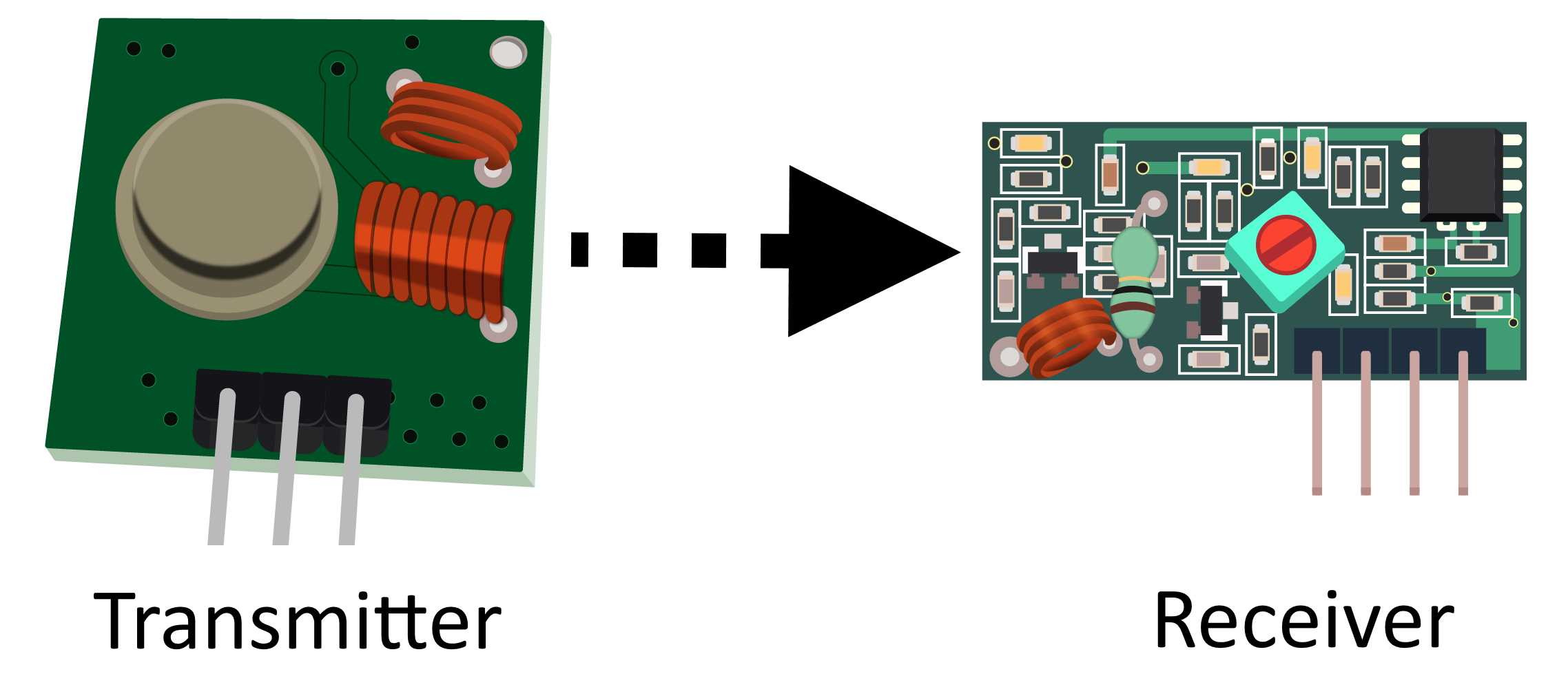
Figure 53: MK transmitter on the left, MK receiver on the right
The module pair does not support two-way communication. If you need two-way communication, you have to use two pairs with a transmitter and a receiver on both sides. The wiring is relatively simple, as we will use only three wires per module. The receiver has four pins, two of them are used for receiving the data. But using two pins for receiving is not reliable because of interference between them. It’s important that the frequencies of the transmitter and receiver match. It doesn’t matter if it’s 315, 330, or 433 MHz; it’s just important that they are the same. Let’s have a look at the parts list for this section.
Parts list for this section:
- 2x Arduino Uno
- 2x USB cable
- XY-MK-5V Receiver module
- FS1000A Transmitter module
- 6x Breadboard Male-to-female jumper wire
We will use one Arduino to send a message to the communications channel. Then, we will use the second Arduino to pick up the message from the channel and send it to the serial port on the computer. Communicating and implementing protocols is usually done with libraries. It is possible to send relatively simple signals with the transmitter and the receiver module without using libraries, but handling complicated messages and checking for errors is a chapter of its own. One of the best libraries for the MK transmitter and the receiver is called VirtualWire. To start using this, you have to download the archive. The archive is located here. Download it and remember where you saved it.
Create a new sketch and click Sketch > Include Library > Add Zip Library. Select the zip archive that you downloaded and the IDE should automatically install the library. If you already installed the library, there is no need for you to install it twice. The Arduino IDE will probably report an error if you try to do so. There is no breadboard in this example, so we’ll show how to wire the modules with tables instead. There are visible markings on the module so we will just go over the connections necessary for our example to work. The transmitter module works on a smaller voltage of 3.3 volts. There are modules available that can receive up to 12 volts, but please check the specification of the module that you purchased just to be on the safe side. Connecting the equipment with voltages that are too big can damage it. There are only three wires on the transmitter module:
Table 6: Transmitter Wiring
Transmitter PIN | Arduino Uno PIN |
ATAD | 12 |
VCC | 3.3 V |
GND | GND |
The receiver module has four pins, but the best results are when we use only three wires. Let’s have a look at the pins:
Table 7: Receiver wiring
Receiver PIN | Arduino Uno PIN |
VCC | 5 V |
DATA (next to VCC) | 11 – Connect just one data pin! |
DATA (next to GND) | 11 – Connect just one data pin! |
GND | GND |
When connecting the receiver, connect just one of the data pins to Arduino pin 11. Now that the wiring is set up, we will interchange messages and then print the messages to the Serial port. We will have a look at the transmitter code first:
#include <VirtualWire.h> // connect the ATAD (data reverse) to pin 12 // greater speed smaller reliability // smaller speed greater reliability // 2000 bits per second is fine for most of the applications int bits_per_second_speed = 2000; void setup() { // initialize VirtualWire vw_setup(bits_per_second_speed); } void loop() { send("This Totally Works!"); delay(1000); } void send (char *message) { // send the message vw_send((uint8_t *)message, strlen(message));
// wait until the message is transmitted vw_wait_tx(); } |
The receiver code:
#include <VirtualWire.h> // connect just one of the DATA wires to pin 11 // transmission speeds have to match int bits_per_second_speed = 2000; // buffer for storing incoming messages byte message[VW_MAX_MESSAGE_LEN]; // we'll save received message size, initial value is max byte messageLength = VW_MAX_MESSAGE_LEN; void setup() { // initialize serial communication with the computer Serial.begin(9600);
// just to let us know that something is going on Serial.println("Initializing device"); // initialize vw_setup(bits_per_second_speed); // starting the receiver vw_rx_start(); Serial.println("VirtualWire receiver started ..."); } void loop() { // not blocking if (vw_get_message(message, &messageLength)) { Serial.print("Incoming: ");
// print every byte for (int i = 0; i < messageLength; i++) { Serial.write(message[i]); }
Serial.println(); } } |
This example might not look like something special, but, believe it or not, the previous example is a basis for a lot of Arduino-based DIY solutions, ranging from home-based automation to security and remote sensing.
The main advantage of the module is that it is extremely cheap and has a relative good range with a soldered-on antenna. The antenna can be something as simple as a wire with a defined length. There are even cases in which people claim that they managed to get the information up to 100 meters or 110 yards.
In reality, it is really dependent on the wall type that you have in between. If it’s a thick, reinforced concrete wall, you probably won’t go through it. But for a regular home and a reasonable distance, the MK modules are just fine. In the next section, we will look at a more robust piece of wireless technology that works on much higher speeds and can communicate both ways (and not always from transmitter to the receiver).
Using nRF24L01+ Data Transceivers
With the nRF24L01+, the data can go both ways at the same time. There are no dedicated emitter and receiver circuits. The frequency at which the transceivers operate is 2.4 GHz and is in the range of the usual home wireless Internet access equipment.
Compared to the MK modules from the previous section, the most difficult thing with them is the wiring. Wiring is also dependent upon the library that we are using. There are several libraries available. The most commonly used one at the time of writing is the RF24.
To install the library, download the file from Github here and remember where you saved it. Create a new sketch and click Sketch > Include Library > Add ZIP Library. Select the zip archive that you downloaded and the Arduino IDE should automatically install the library. If you decide on some other library, please check how the module should be connected. Next, we will go through the wiring scheme. Let’s have a look at the module:
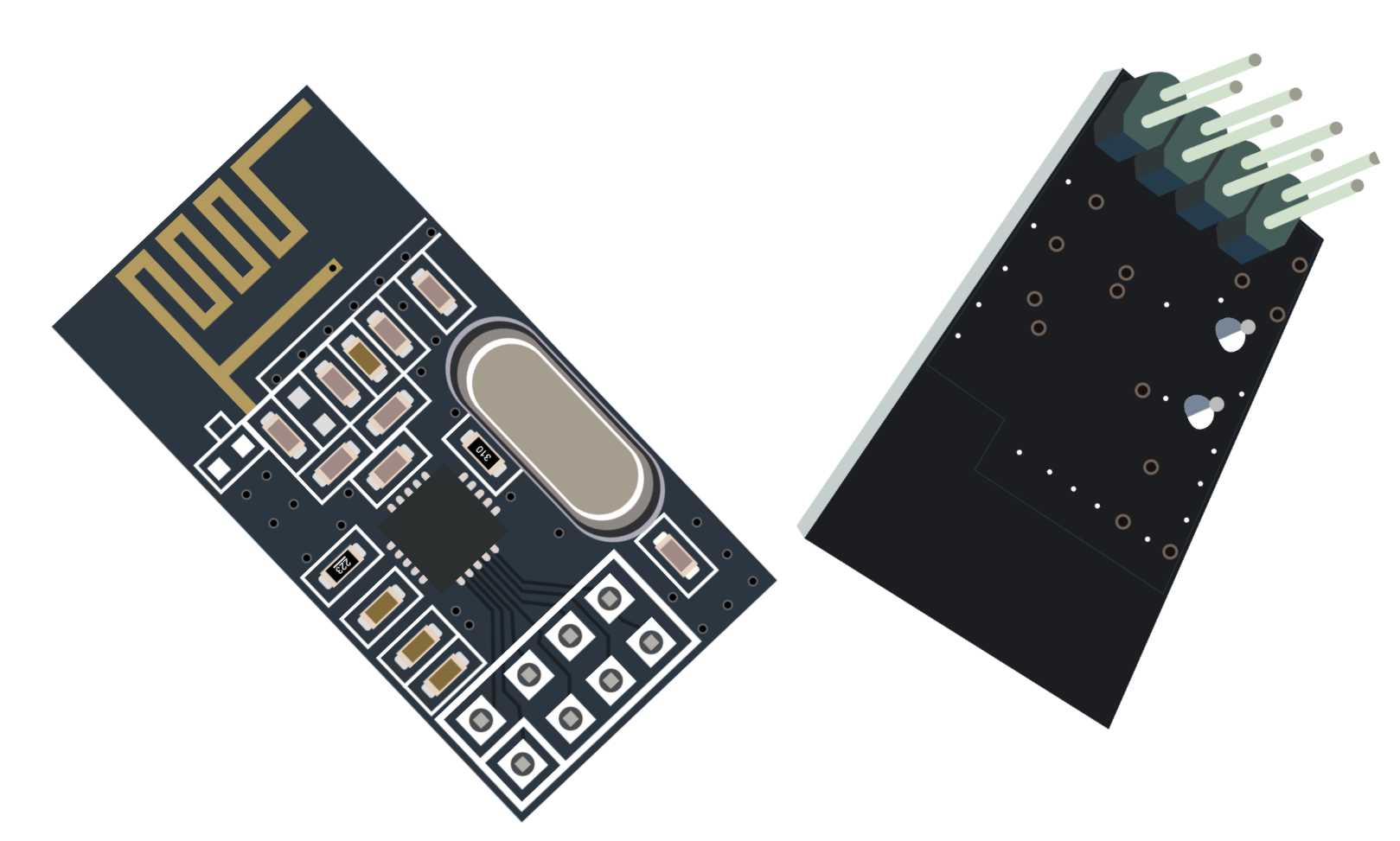
Figure 54: nRF24L01+ front and back side view
The easiest way to connect the pins is to turn the module so that you see the backside of it. The backside is the side with the pins sticking out:
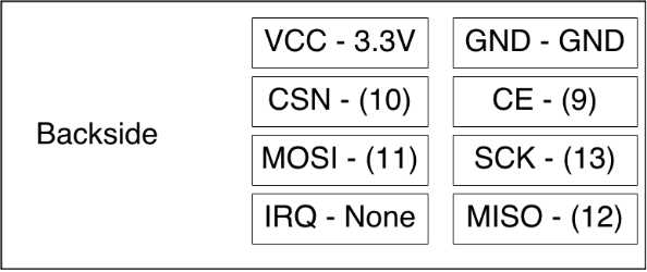
Figure 55: nRF24L01+ wiring
There are many wiring schemas available online, but most of them require you to look for the pin from the other side. This image represents how you see the pins when you turn it to the backside. It will be a lot easier for you to connect the module this way. There are some versions of the nRF24L01+ available online with this layout printed on the backside next to the pins. Use the previous figure if you don’t have the version with the print. Next to the name of the pin is the name of the destination pin on the Arduino. Here are detailed explanations with every pin on the transceiver module:
Table 8: nRF24L01+ Pin Description of Pins and Wirings with the Arduino
Receiver PIN | Description | Destination Pin on Arduino |
VCC | Pin for 3.3V + | 3.3 V |
GND | Ground | GND |
CSN | Chip Select Not. If this is low, chip responds to SPI commands. Serial Peripheral Interface (SPI) Bus is a serial synchronous communication standard. | 10 |
CE | Chip enable. If it’s high, the module is sending or listening. | 9 |
MOSI | Master-Out-Slave-In. Sends the data from microcontroller to the device. | 11 |
SCK | SPI Shift Clock; used for synchronization of data during the transfer. | 13 |
IRQ | Optional Interrupt Request pin. | This pin is not connected in our examples. |
MISO | Master-In-Slave-Out. Sends the data from the device to the microcontroller. | 12 |
We will need two Arduino boards in this example and two transceiver modules. We will also need 14 wires to connect both Arduino boards. We won’t make very complex protocols in the example. Every Arduino will read the data and send the data.
We will adapt one of the Arduino boards to display the information in the Serial Monitor so that we know what’s going on. We will give names to the microcontrollers. The first one will get a simple designation “A”. The data that we will send over will be the basis for a simple protocol. We will put the source and the destination info into packages plus some randomly generated data like temperature and light. We won’t set up the wiring to measure the values because the focus in this example is on the networking part.
#include <SPI.h> #include <nRF24L01.h> #include <RF24.h> // set up nRF24L01 radio on SPI bus plus pins 9 & 10 RF24 radio(9, 10); // channel designations, put as many as you need, 2 are enough for this // every transceiver can have one out and up to 5 read channels const uint64_t pipes[2] = { 0xF0F0F0F0E1LL, 0xF0F0F0F0D2LL }; typedef struct { char source; char destination; float temperature; int light; } TotallyCustomData; TotallyCustomData data_out, data_in; void setup(void) { Serial.begin(9600); radio.begin(); // 15 millis delay for channel to settle, try to send 15x radio.setRetries(15, 15); radio.openWritingPipe(pipes[0]); radio.openReadingPipe(1, pipes[1]); radio.startListening(); } void loop(void) { data_out.source = 'A'; data_out.destination = 'B'; data_out.temperature = random(30); data_out.light = random(100); // check if the data is available if (radio.available()) { bool done = false; // read the data until finished while (!done) { done = radio.read(&data_in, sizeof(data_in)); // print the data Serial.println("Received data"); Serial.print("source = "); Serial.println(data_in.source); Serial.print("destination = "); Serial.println(data_in.destination); Serial.print("temperature = "); Serial.println(data_in.temperature); Serial.print("light = "); Serial.println(data_in.light); Serial.println(""); } }
// send the data after reading is done
// stop listening so we can talk. radio.stopListening(); bool ok = radio.write(&data_out, sizeof(data_out)); radio.startListening(); // just so that we don't send too much data delay(1000); } |
Let’s look at the code that we are going to put on the Arduino board “B”:
#include <SPI.h> #include "nRF24L01.h" #include "RF24.h" // set up nRF24L01 radio on SPI bus plus pins 9 & 10 RF24 radio(9, 10); // radio pipe addresses for the two nodes to communicate. const uint64_t pipes[2] = { 0xF0F0F0F0E1LL, 0xF0F0F0F0D2LL }; typedef struct { char source; char destination; float temperature; int light; } TotallyCustomData; TotallyCustomData data_out, data_in; void setup(void) { radio.begin(); // 15 millis delay for channel to settle, try to send 15x radio.setRetries(15, 15); radio.openWritingPipe(pipes[1]); radio.openReadingPipe(1, pipes[0]); radio.startListening(); } void loop(void) { data_out.source = 'B'; data_out.destination = 'A'; data_out.temperature = random(30); data_out.light = random(100); if (radio.available()) { bool done = false; while (!done) { done = radio.read(&data_in, sizeof(data_in)); } }
// after data reading, write something // transceiver works in both directions, so cool :) // stop listening so we can talk. radio.stopListening(); bool ok = radio.write(&data_out, sizeof(data_out)); radio.startListening(); // just so that we don't send too much data delay(1000); } |
Be careful when uploading the examples because it can easily happen that you upload the code to the wrong board! Double-check the Serial ports before uploading the sketch to the Arduino board.
The transmission distance depends upon the wall setup that you have at your home. So there will be border situations where you will have a feeling that you are missing just a few more inches for everything to work. Try to reduce the length of the package in those situations. In our example, the message contains eight bytes but the payload size is by default set to 32 bytes. Try reducing the payload length to eight in the setup function.
void setup(void) { … radio.setPayloadSize(8); … |
One other problem that appears on the Arduino Uno boards is that the voltage on the 3.3V pin is not very stable and, as soon as the transmission starts, there is a very high message loss rate. Some people are using a separate 3.3V power source.
Some solder a 10-μF capacitor across 3.3V and the GND pin on the transceiver. Message loss rate is reduced by 25 percent with the capacitor. There are also versions of the module that have a larger antenna similar to one available on home routers. The module used in the example has an antenna printed on the board of the transceiver.
Connecting to Wireless with ESP8266 Chip
There is a lot of talk and articles about the Internet of Things (IoT), the devices connecting to the IoT, and the exchanging of data with other devices and computers. The MK chips and the nRF24 chips mentioned in the previous sections usually support an infrastructure in which we have one home hub that gathers the signals from the other devices and then uses the messages coming in from those device to send them further to other devices, with more computing power inside the home network or somewhere online.
Most Internet access today is over the wireless router available in our homes. Now, the question arises, wouldn’t it be great if we could make our smart devices use the already available wireless infrastructure to send the data around? Up until recently, those devices were pretty expensive and it kind of defeated the whole purpose if those devices were more expensive than the Arduino board. Actually, a new member was recently added to the Arduino family that can do all that, namely, the Arduino Yún. But the price mark for it is more than two times greater than the Arduino Uno. An excellent choice with a very reasonable price is the ESP8266 Wi-Fi transceiver. It actually looks very similar to the nRF24 chip:
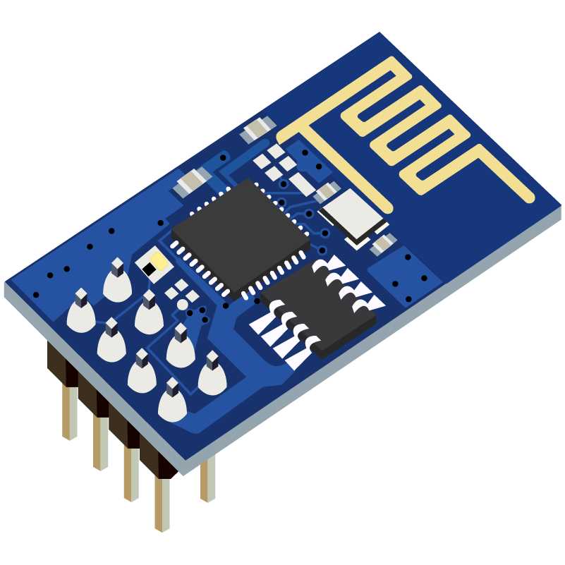
Figure 56: ESP8266 front side view
In this example, we will use multiple wires, the proto-board, the ESP8266 module, and the Arduino Uno. The ESP8266 is a 3.3 V circuit, and you should always connect all of the pins to 3.3 V sources as none of the pins is 5 V compatible. All of the pins from now on are stepped down to 3.3 V when connected, even if the text states connect to Arduino pin.
Parts list for this section:
- 1x Arduino Uno
- 1x USB cable
- ESP8266 wireless chip
- Breadboard
- 2x 1K-Ohm resistor
- 2x 3.3V Zener diode, for stepping down the voltage from Arduino 5V to chip 3.3V
- 5x Breadboard male-to-female jumper wire
- 6x Breadboard male-to-male jumper wire
- A working home wireless network
The pin names on the EXP8266 are shown on the following figure:
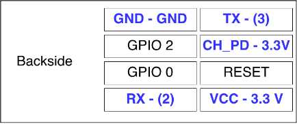
Figure 57: ESP8266 backside side view with pin names
Let’s jump to wiring right away:
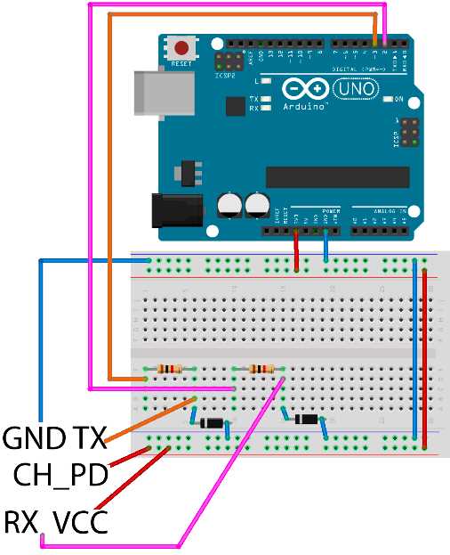
Figure 58: ESP8266 wiring
Unlike the previously used chip, this chip requires only five wires to get connected. The pins that need to get connected are marked with a blue color in the previous figure. The chip works so that we send it textual commands over the serial port, but the command list is very long, and it’s a bit tedious work, so it’s best that we use a library. The library is available for download on Github here. Create a new sketch and click Sketch > Include Library > Add ZIP Library. Select the zip archive that you downloaded and the Arduino IDE should automatically install the library.
However, the library will not work out of the box and there is a little bit of tweaking that we need to do before it is suitable for our use. But, before doing that, let’s take a short step back. The Arduino uses TX and RX pins for serial communication. We use those two pins to transfer the programs to the board and to receive messages from the Arduino. So, if we want the Arduino to communicate over serial with other devices, we have to use an Arduino library called SoftwareSerial that allows us to turn any pair of pins into serial communication pins.
In our example, we will use the real Arduino TX and RX pins to show the messages in the Serial Monitor, and we will turn pin 3 into the software version of RX and pin 2 into the software version of TX. The software serial library comes with the Arduino so you don’t have to install additional libraries. There is a little tweak that we have to make in the WeeESP8266 library before we use it in our examples. First, you have to find the folder where the Arduino libraries are located:
Table 9: Arduino libraries folder location by platform
Platform | Location |
Windows | My Documents\Arduino\libraries\ |
Linux | Documents/Arduino/libraries/ |
Mac | Documents/Arduino/libraries/ |
Then, you have to find the folder inside the libraries folder where the newly installed library is located. It is called ITEADLIB_Arduino_WeeESP8266-master or ITEADLIB_Arduino_WeeESP8266. Open the file called ESP8266.h with a raw text editor. Look for the following line:
// #define ESP8266_USE_SOFTWARE_SERIAL |
Remove the comments from the beginning of the line. If this line remains commented, you will not be able to upload the sketch to the Arduino board because the following example will not compile. We will start with something relatively simple since, for starters, we just want our Arduino to access our wireless network and obtain an IP address:
#include <ESP8266.h> #include <SoftwareSerial.h> // define the access data for your home wifi #define SSID "YourSSID – Name of your wifi connection" #define PASSWORD "YourWirelessPassword" // initialize a softwareserial with rx - 3 and tx - 2 SoftwareSerial mySerial = SoftwareSerial(3, 2); // initialize the wifi to work with mySerial ESP8266 wifi(mySerial); void setup(void) { Serial.begin(9600); Serial.println("Setup begin"); Serial.print("FW Version: "); Serial.println(wifi.getVersion().c_str()); if (wifi.setOprToStation()) { Serial.println("to station ok"); } else { Serial.println("to station err"); } if (wifi.joinAP(SSID, PASSWORD)) { Serial.println("Join AP success"); Serial.print("IP: "); Serial.println(wifi.getLocalIP().c_str()); } else { Serial.println("Join AP failure"); } Serial.println("setup end"); } void loop(void) { // we'll leave the loop empty } |
If everything went fine, you should see an IP address that your router has assigned you. This is sort of a simple Hello World for this component. But, if you take a step back and look at all of the possibilities with the protocols and emission standards, getting everything to connect to a home wireless network, this example is really something. Your Arduino board is becoming an actual IoT device, just like that.
Getting Data Online with ESP8266 Chip
The wiring and the components are the same as in the previous section. The focus will be more on the programming. The task is to send the data from the Arduino over a TCP to a remote server. To make it simple, we are just going to display the sent data on the server side. In this example, we will create a simple server, too. This is a bit out of scope for the book, and we didn’t mention any Python programming up until now, but please try to find a computer with Python installed or install it by following the instructions available here. Note that, on some systems, you will have to add the python executable to the PATH variable, but that is all outside of the scope of this book. Please follow the official documentation available under the previous link. After that, create a file called simple_service.py and remember the location where you saved it on the disk:
#!/usr/bin/env python """ A simple server """ import socket host = '0.0.0.0' port = 31233 backlog = 10 size = 1024 s = socket.socket(socket.AF_INET, socket.SOCK_STREAM) s.bind((host, port)) s.listen(backlog) # do until script is interrupted while 1: # accept incoming connections client, address = s.accept() # get the sent data data = client.recv(size) # print received data print("request: " + data) # close the connection client.close() |
If you have Python installed, you can just run the script from the command line:
$ python simple_service.py |
This covers the server side of the example. Also, be very careful with the firewall setting. If there is a firewall between the server and the ESP chip, the example will not work. Now that the server side is taken care of, let’s look at the Arduino code:
#include <ESP8266.h> #include <SoftwareSerial.h> // define the access data for your home wifi #define SSID "YourSSID" #define PASSWORD "YourPassword" // initialize a softwareserial with rx - 3 and tx - 2 SoftwareSerial mySerial(3, 2); // the endpoint of the service // in my case it's 192.168.1.2 #define HOST_NAME "192.168.1.2" #define HOST_PORT (31233) ESP8266 wifi(mySerial); void setup(void) { Serial.begin(9600); Serial.println("Setup begin");
Serial.print("FW Version:"); Serial.println(wifi.getVersion().c_str());
if (wifi.setOprToStationSoftAP()) { Serial.println("to station + softap ok"); } else { Serial.println("to station + softap err"); }
if (wifi.disableMUX()) { Serial.println("single ok"); } else { Serial.println("single err"); }
Serial.println("setup end"); }
void loop(void) { uint8_t buffer[128] = {0};
if (wifi.createTCP(HOST_NAME, HOST_PORT)) { Serial.println("create tcp ok"); } else { Serial.println("create tcp err"); }
char *request = "This could be anything!"; Serial.println(request);
wifi.send((const uint8_t*)request, strlen(request));
uint32_t len = wifi.recv(buffer, sizeof(buffer), 1000);
if (len > 0) { Serial.print("Received:["); for(uint32_t i = 0; i < len; i++) { Serial.print((char)buffer[i]); } Serial.println(""); Serial.println("]"); }
delay(10000); } |
If everything went fine, you should see the data coming in from the Arduino. In our example, it will look something like the following:
$ python echo_service.py request: This could be anything! |
This was an example in which the ESP chip is sending the data to a server. But ESP is actually a really powerful chip. It even has its own firmware and you can upgrade it if you want. There are two GPIO pins available on the board and there are a lot of examples online where the Arduino is not even needed and the chip can function on its own. To prove how powerful this chip actually is, we are going to build a small TCP echo server that reverses back the data sent to it. Here is the code for the Arduino:
#include <ESP8266.h> #include <SoftwareSerial.h> // define the access data for your home wifi #define SSID "YourSSID" #define PASSWORD "YourPassword" // initialize a softwareserial with rx - 3 and tx - 2 SoftwareSerial mySerial(3, 2); ESP8266 wifi(mySerial); void setup(void) { Serial.begin(9600); Serial.println("setup begin"); Serial.print("FW Version:"); Serial.println(wifi.getVersion().c_str()); if (wifi.setOprToStationSoftAP()) { Serial.println("to station + softap ok"); } else { Serial.println("to station + softap err"); } if (wifi.joinAP(SSID, PASSWORD)) { Serial.println("Join AP success"); Serial.print("IP: "); Serial.println(wifi.getLocalIP().c_str()); } else { Serial.println("Join AP failure"); } if (wifi.enableMUX()) { Serial.println("multiple ok"); } else { Serial.println("multiple err"); } if (wifi.startTCPServer(8090)) { Serial.println("start tcp server ok"); } else { Serial.println("start tcp server err"); } if (wifi.setTCPServerTimeout(10)) { Serial.println("set tcp server timout 10 seconds"); } else { Serial.println("set tcp server timout err"); } Serial.print("setup end, ready to receive requests"); } void loop(void) { uint8_t buffer[128] = {0}; uint8_t buffer_reverse[128] = {0}; uint8_t mux_id; uint32_t len = wifi.recv(&mux_id, buffer, sizeof(buffer), 100); if (len > 0) { Serial.print("Status:["); Serial.print(wifi.getIPStatus().c_str()); Serial.println("]"); Serial.print("Received from :"); Serial.print(mux_id); Serial.print("["); for (uint32_t i = 0; i < len; i++) { Serial.print((char)buffer[i]); } Serial.println("]");
for (int c = len - 1, d = 0; c >= 0; c--, d++) { buffer_reverse[d] = buffer[c]; }
if (wifi.send(mux_id, buffer_reverse, len)) { Serial.println("send back ok"); } else { Serial.println("send back err"); } if (wifi.releaseTCP(mux_id)) { Serial.print("release tcp "); Serial.print(mux_id); Serial.println(" ok"); } else { Serial.print("release tcp"); Serial.print(mux_id); Serial.println(" err"); } Serial.print("Status:["); Serial.print(wifi.getIPStatus().c_str()); Serial.println("]"); } } |
When you start the example, you should see what IP address was assigned to the Arduino with the ESP chip in the Serial Monitor tool. Then, we will use the Telnet tool to connect to it on the port 8090. The ESP should return reversed characters that we type in. Remember, there is a 10-second timeout for you to type something in and hit Enter:
$ telnet 192.168.1.5 8090 Trying 192.168.1.5... Connected to unknown-18-fe-34-9b-79-87.lan. Escape character is '^]'. !sklof lla s'tahT That's all folks!Connection closed by foreign host. |
This example is the final one for showing the capabilities of the ESP module and it also concludes the part about the Networking with the Arduino. This is also the last example in the book.
- 1800+ high-performance UI components.
- Includes popular controls such as Grid, Chart, Scheduler, and more.
- 24x5 unlimited support by developers.