
Arduino Succinctly®

CHAPTER 5
Measuring Environment Conditions
By now, the only input to the Arduino that we covered is the reacting to a press of a button. This is a relatively simple reading in which the current is either present or not. Based upon the current presence, we can then do various actions. Arduino is capable of far more than just detecting whether or not a button is pressed; it can be used to measure the environment conditions. Environment measurements are rarely simple binary values. For instance, the light level in the room might be somewhere between totally dark and very bright from the sun coming in from a glass ceiling. For instance, we could turn on the light if the light level drops below a predefined value. In this section, we will explain how to measure the air temperature, air humidity, and the barometric pressure as well as how to detect the light levels. As in the previous chapters, we will use widely available and inexpensive components to make the examples. Let’s start with simple air temperature readings.
Measuring Air Temperature
We’ll start by using a simple electronic component called the Thermistor. The basic principle behind this component is that it gives different resistance to the passing current based upon the surrounding temperature. There are two basic types of Thermistors:
- Negative Temperature Coefficient - Resistance drops as temperature increases
- Positive Temperature Coefficient - Resistance increases as temperature increases
In our example, we’ll use the Negative Temperature Coefficient type. The 10K Ohm NTC 5mm Thermistor is a good choice when it comes down to availability, precision, and price:

Figure 34: 10K Ohm NTC 5mm Thermistor
Parts list for this section:
- Arduino Uno
- USB cable
- 1x 10K Ohm NTC 5mm Thermistor
- 1x 10k Ohm resistor
- Breadboard
- 3x Breadboard jumper wire
The behavior of the Thermistor is determined by the Steinhart-Hart equation. The most important parameter in the equation is the measured resistance. The measured resistance is not a digital value of HIGH and LOW. It has a whole range of values between the HIGH and the LOW. Arduino uses analogue pins to measure those values. With the binary pins, we only get the information if the current is present on some pin or not. With the analogue, we get a value from a range. In Arduino, this range is from 0 to 1023—meaning that there are 10 bits to represent the input current on the pin. Analogue pins can also be used for output, but then they behave as regular digital pins, and it is not possible to read analogue values from them. Most of the time, you won’t have problems with this behavior, but keep in mind that it could happen. Let’s start with the wiring for the example:
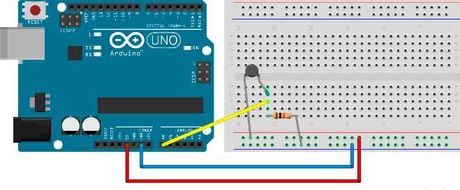
Figure 35: Wiring for 10K Ohm Thermistor
The previous example uses just three wires instead of five. Replace the longer pins of elements with wires if you desire. It’s the usual way of wiring in the literature and schematics but, for smaller circuits, it’s perfectly fine not to use too many wires. We’ll output the readings to the Serial port. The most complicated part of this example is reading the input current and then turning this reading into the temperature. Most of the examples found online use a couple of one-liners and then magically show the output to the user. You’ll learn more by understanding the code than by just copying and pasting the example. So we are going to go along with this implementation:
// we need advanced math functions #include <math.h> int reading;
void setup() { // Initialize serial communication at 9600 bit/s Serial.begin(9600); } void loop() { reading = analogRead(A0);
float kelvins = thermisterKelvin(reading); float celsius = kelvinToCelsius(kelvins); float fahrenheit = celsiusToFahrenheit(celsius);
Serial.print("kelvins = "); Serial.println(kelvins);
Serial.print("celsius = "); Serial.println(celsius);
Serial.print("fahrenheit = "); Serial.println(fahrenheit);
Serial.println("");
delay(3000); } float thermisterKelvin(int rawADC) { // Steinhart-Hart equation // 1/T = A + B (LnR) + C(LnR)ˆ3
// LnR is the natural log of measured resistance // A, B, and C are constants specific to resistor
// we'll use: // T = 1 / (A + B(LnR) + C(LNR)ˆ3)
// we are using long because Arduino int goes up to 32 767 // if we multiply it by 1024, we won't get correct values long resistorType = 10000;
// input pin gives values from 0 - 1024 float r = (1024 * resistorType / rawADC) - resistorType;
// let' calculate natural log of resistance float lnR = log(r);
// constants specific to a 10K Thermistor float a = 0.001129148; float b = 0.000234125; float c = 0.0000000876741;
// the resulting temperature is in kelvins float temperature = 1 / (a + b * lnR + c * pow(lnR, 3));
return temperature; } float kelvinToCelsius(float tempKelvin) { return tempKelvin - 273.15; } float celsiusToFahrenheit(float tempCelsius) { return (tempCelsius * 9.0)/ 5.0 + 32.0; } |
After running the example, wrap your fingers around the thermistor and hold it for a while. Your body temperature should be higher than the air’s temperature, so you’ll see the change in the readings. We used the Serial Monitor in the previous examples.
Detecting Light Levels
Light level detection is pretty similar to temperature measuring. The component that we will use in this section becomes more conductive with the light shining upon it:
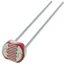
Figure 36: Photo Resistor
Parts list for this section:
- Arduino Uno
- USB cable
- 1x GL5528 Photo Resistor or any 10K Ohm Photo Resistor
- 1x 10k Ohm resistor
- Breadboard
- 3x Breadboard jumper wire
The wiring for the example looks similar to the one for measuring the air temperature:
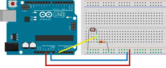
Figure 37: Wiring a photo resistor
Let’s just skip to code right away and explain it later:
// we'll store reading value here int reading;
void setup() { // initialize serial communication at 9600 bit/s Serial.begin(9600); } void loop() { reading = analogRead(A0);
// we'll measure the input values and map 0-1023 input // to 0 - 100 values int lightLevel = map(reading, 0, 1023, 0, 100);
Serial.print("light = "); Serial.println(lightLevel);
delay(3000); } |
The first question that might come to mind is what does this number mean? It goes from 0 to 100, so one might even think of it as a percentage. But the question is, compared to what? If the photo resistor is connected in a circuit (as in the previous figure), it can measure light levels of up to 10 lux. Lux is a measurement for luminance. 10 lux is not a lot if you look at the following table; actually, it’s pretty dark and you can’t measure the differences between bright and brighter:
Table 1: Lux levels and a description of the light levels
Lux Level | Description |
0.27 – 1.0 | Moonlight |
3.4 | Dusk |
10 lux | Very dark and rainy day |
50 lux | Regular light level in a living room |
320 – 500 | Office light |
1000 | Full daylight with no direct sun |
100 000 | Sunlight |
In our example, we are not measuring light levels in lux units but, rather, are simply mapping the reading to a percentage. Percentages are easily understandable, and it’s easy to check on which light levels we want to take action on. However, with the previous setting, we won’t be able to measure very bright light. There’s a neat trick to get around this situation. If you put a 1k Ohm resistor into the circuit instead of the 10, you will be able to get differences in readings on a much higher level, and you will be able to differentiate between the bright and brighter.
If you want to measure the exact lux levels, you will have to carefully look into the resistor specification and map the voltages from the specification to your readings. This work is a bit tedious, and it’s used only in very specific situations such as photography. For the regular use case such as “Is there a light on?” or something similar, it’s advisable that you simply use the percentages and adapt the resistor in the circuit to the light levels that you want to measure. Basically, use a 10K resistor if you want to differentiate between the dark and darker, or a 1K resistor if you want to differentiate between the light and lighter. Most readers with an engineering background might prefer the lux unit, but mapping the voltage to simple percentages is more than sufficient for day-to-day use.
Using Temperature and Humidity Sensor
In the earlier section, we used an element called a thermistor to measure the temperature. The electronics behind it were relatively simple: There’s an element and we’re just interpreting the current levels that we get. For some usages, having a simple element just doesn’t cut it, and using the basic elements significantly increases the number of elements that we have to put into our electronics. So the manufacturers started to build separate components that can then communicate with the Arduino, which then communicates with other devices, and so forth. We will start with something relatively simple such as measuring the temperature in order to go through the whole process of using a separate component with the Arduino.
There are many temperature sensors that can communicate with the Arduino and exchange information with it. One of the most commonly used and relatively inexpensive is the DHT11 sensor. Besides the temperature, it can measure the relative humidity. Programming it might be a bit tricky, and we would have to go deep into the specification to do any work with it. So we are going to use a library to do the dirty work for us. Here’s the DHT11 module:
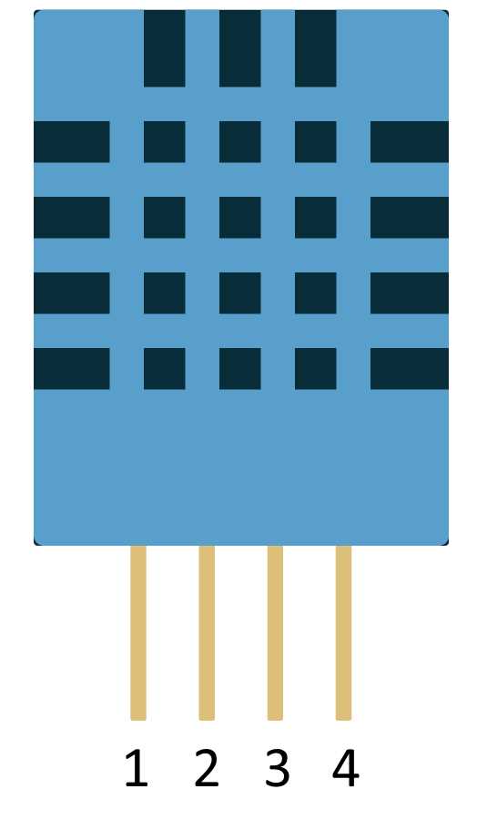
Figure 38: DHT11 temperature and humidity sensor
The figure shows markings on the pins so that it’ll be easier for you to connect the sensor to the board when you start setting up the example. You don’t have to worry about turning the sensor the wrong way around because the front side shown in the figure has holes whereas the back side is smooth. As in every section, we’ll start with the parts.
Parts list:
- Arduino Uno
- USB cable
- DHT11 temperature and humidity sensor
- 10K Ohm resistor
- Breadboard
- 5x Breadboard jumper wire
And here’s the wiring:
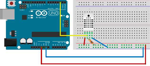
Figure 39: DHT22 (depicted) and the DHT11 have same wiring
There are variations of the DHT, such as DHT22. We depicted the wiring with the DHT22 just so you are aware that there are other sensors with almost the same name but they function totally different (although the wiring is the same). We’ll look at that when we discuss programming.
To hook everything up, we’ll need to download a library. Download the file located in Github here and remember where you saved it. Create a new sketch and after that, click Sketch > Include Library > Add ZIP Library. Select the zip archive that you downloaded and the IDE should automatically install the library. Here’s the code that goes along with the example. Make sure you change the DHTTYPE constant to the type you’re using:
#include "DHT.h" // to use the library we have to define some constants // what pin are we going to use #define DHTPIN 2 // what type of sensor are we going to use // possible: DHT11, DHT22, DHT21 // be careful to set it correctly #define DHTTYPE DHT11 // instantiate DHT sensor DHT dht(DHTPIN, DHTTYPE); void setup() { // we'll print measurements to serial Serial.begin(9600);
// start the sensor dht.begin(); } void loop() { // it takes around 2 seconds for the sensor to update data delay(2000); // read humidity float h = dht.readHumidity();
// Read temperature as Celsius float t = dht.readTemperature();
// Read temperature as Fahrenheit float f = dht.readTemperature(true);
// check the value if (isnan(h) || isnan(t) || isnan(f)) { Serial.println("Failed to read, reading again!"); } else { // compute heat index // heat index works only with Fahrenheit float hi = dht.computeHeatIndex(f, h);
Serial.print("Humidity %: "); Serial.println(h);
Serial.print("Temperature *C: "); Serial.println(t);
Serial.print("Heat index *C: "); Serial.println(fahrenheitToCelsius(hi));
Serial.print("Temperature *F: "); Serial.println(f);
Serial.print("Heat index *F: "); Serial.println(hi);
Serial.println(); } } float fahrenheitToCelsius(float tempF) { return (tempF - 32) / 1.8; } |
Many Arduino sensors work similarly to this one. You download a library, hook up the sensor, and then start reading the data. There are many libraries out there for various Arduino sensors. This section described the standard procedure when working with more complex sensors.
Measuring Barometric Pressure
This is not a book on physics, so we won’t talk a lot about what air pressure is. Air also has weight, and surfaces exposed to the atmosphere experience pressure of the air. There are two main ways to use barometric pressure. One way is to track changes in the weather. A second way is to measure the change in the altitude between two points with a known pressure.
When observing the weather, there are a lot of weather stations located either very high in the mountains, at the sea level, or below it (like in Death Valley). No matter where we take the measurement, we can calculate what the pressure would be like on the sea level if we know the height above the sea level. So, in the weather forecast, all of the air pressure values are usually expressed at the sea level. The standard pressure is 1013.25 millibar or 29.92 inHg. We can then quickly determine if a certain point is below the usual pressure value or above it. Depending upon the location we are currently on, we can even use the movements of the air pressure to predict the weather.
Air gets thinner when it goes higher into the atmosphere. Today, sensors can measure relatively small vertical movements; usually the precision is within three feet or one meter. The main component we will use in this section is the BMP180 Barometric Pressure sensor:
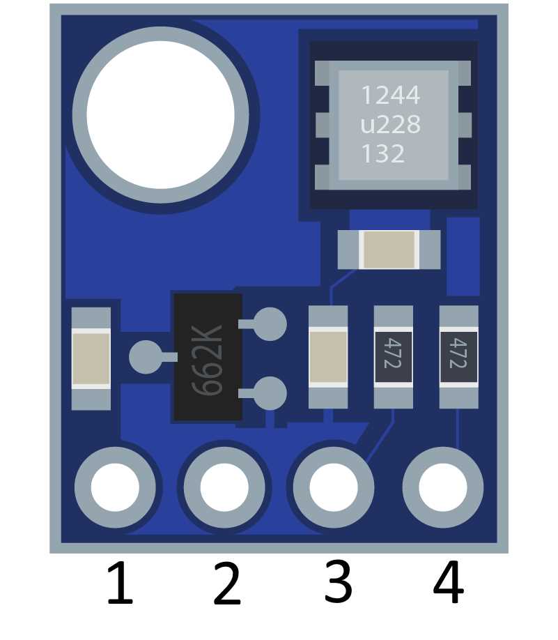
Figure 40: BMP180 barometric pressure sensor
Parts list for this section:
- Arduino Uno
- USB cable
- BMP180 barometric pressure sensor
- Breadboard
- 4x Breadboard jumper wire
The external pin goes to a 3.3V power source on Arduino. Pin 2 goes to the ground. Pin 3 goes to A5 and Pin 4 goes to A4. Note that there are varieties of the chip and that some of them have five pins or more. In a five-pin version, the first pin is simply ignored and the rest is the same as in the previous figure. If there are more than five pins, look up the manufacturer’s documentation. Let’s look at the wiring:
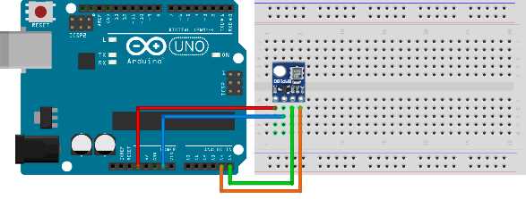
Figure 41: BMP180 sensor wiring
Reading the value is a bit more complicated. Communication with the module would be a labor-intensive process. So to hook everything up, we’ll need to download a library. Download the file located on Github here and remember where you saved it. Create a new sketch and click Sketch > Include Library > Add ZIP Library. Select the zip archive that you downloaded and the IDE should automatically install the library. Here’s the code that goes along with the example:
#include <SFE_BMP180.h> // SFE_BMP180 library is not enough // we have to include the wire to communicate with the sensor #include <Wire.h> // SFE_BMP180 object sensor: SFE_BMP180 sensor; // altitude of my home in meters // change this to your own altitude!!! // you will get strange reading otherwise #define ALTITUDE 178.0 // we'll keep track of previous measured pressure // so that we can calculate relative distance double previous_p = 0; void setup() { Serial.begin(9600); Serial.println("INIT ..."); // begin initializes the sensor and calculates the calibration values if (sensor.begin()) { Serial.println("BMP180 init OK"); } else { Serial.println("BMP180 init FAILED!!!"); // stop the execution delay(1000); exit(0); } } void loop() { // we'll make a reading every 5 seconds delay(5000); byte waitMillis, status; double temp, p, p0, a; // weather reports use sea level compensated pressure // find out your altitude to get the readings right Serial.println(); Serial.print("ALTITUDE: "); Serial.print(ALTITUDE); Serial.print(" m "); Serial.print(ALTITUDE * 3.28084); Serial.println(" feet"); // to read the pressure, you must read the temperature first // ask the sensor when can we get a temperature reading // if o.k. we get waitMillis, otherwise 0 waitMillis = sensor.startTemperature(); if (waitMillis == 0) { Serial.println("Temperature reading not ready"); return; } // wait for as long as the sensor says delay(waitMillis); // retrieve the temperature measurement into temp // function updates waitMillis again waitMillis = sensor.getTemperature(temp); if (waitMillis == 0) { Serial.println("Error reading temperature"); return; } // current temperature values in different units Serial.print("TEMPERATURE: "); Serial.print(temp); Serial.print(" *C "); Serial.print((9.0 / 5.0) * temp + 32.0); Serial.println(" *F");
// start a pressure measurement: // precision from 0 to 3, precise readings take more time // we get millis how long to wait for the measurement waitMillis = sensor.startPressure(3); if (waitMillis == 0) { Serial.println("Error starting pressure reading"); return; } delay(waitMillis); // Retrieve the completed pressure measurement: // Function returns 1 if successful, 0 if failure. status = sensor.getPressure(p,temp); if (waitMillis == 0) { Serial.println("Error getting pressure reading"); return; } // pressure data Serial.print("ABSOLUTE PRESSURE: "); Serial.print(p); Serial.print(" mb "); Serial.print(p * 0.0295333727); Serial.println(" inHg"); // sensor returns absolute pressure, which varies with altitude. // in weather reports a relative sea-level pressure is used p0 = sensor.sealevel(p, ALTITUDE);
Serial.print("SEA LEVEL: "); Serial.print(p0); Serial.print(" mb "); Serial.print(p0 * 0.0295333727); Serial.println(" inHg"); // altitude difference from previous reading a = sensor.altitude(p, previous_p); Serial.print("HEIGHT DIFFERENCE FROM PREVIOUS: "); Serial.print(a); Serial.print(" m "); Serial.print(a * 3.28084); Serial.println(" feet");
previous_p = p; } |
The example might give you significantly different readings than the one on the local weather station. Make sure that you find out the sea level height of your home before you run the example. Otherwise, you might be confused by the results. The height is set by using the define command #define ALTITUDE 178.0 in line 12 of the provided example. If you are ever going to build a project that does weather monitoring, this will be one of examples that will come in handy. By now, we talked a lot about the atmosphere. What else can we sense with the Arduino? We’ll talk about it more in the next section.
Detecting Soil Moisture
If you ever had plants, you know that one can occasionally forget to water them. Well, believe it or not, Arduino has this covered too. All you need to avoid that kind of problem is a soil moisture sensor. Soil conductivity properties change with the amount of water contained in the soil, and the sensor measures those properties. The sensor has two components: the probe and the sensor itself.
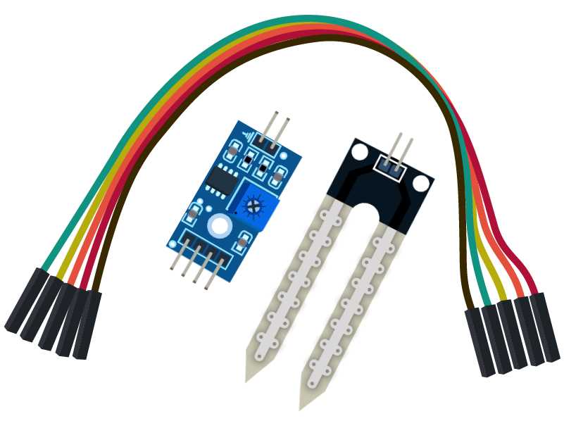
Figure 42: Soil moisture sensor with parts
The wiring between the probe and the sensor is done with two wires. It doesn’t matter how you connect them. We’ll talk about the wiring between the Arduino and the sensor shortly. We won’t use the breadboard in this example.
Parts list for this section:
- Arduino Uno
- USB cable
- YL-96 soil moisture sensor
- 4x wire
- A glass of water to test the functioning
Table 2: YL-96 pins
Pin | Description |
VCC | Pin for connecting 5V + |
GND | Pin for connecting the ground |
DO | Digital output |
AO | Analog output |
Connect the VCC to Arduino 5V, GND to Arduino GND, and DO to digital in 8. Use the following code listing:
// we'll use digital pin 8 int inPin = 8; // we'll store reading here int val; void setup() { // initialize serial communication Serial.begin(9600); // set the pin mode for input pinMode(inPin, INPUT); } void loop() { // read the value val = digitalRead(inPin);
// if the value is low if (val == LOW) { // notify about the detected moisture Serial.println("Moisture detected!"); delay(1000); } } |
Open the Serial Monitor and watch what happens when you put the probe in the glass of water. Remember, this is just a digital reading. The probe can use the analog pins to send the levels of moisture. Reconnect the pins and connect the VCC to Arduino 5V, the GND to Arduino GND, and the AO to Analog in 5 on the Arduino. Use the following code sample:
// we'll store reading from the input here int input; // we'll map the input to the percentages here int val; void setup() { // initialize the serial communication Serial.begin(9600); } void loop() { // read the value from A5 input = analogRead(A5); // map it to percentage val = map(input, 1023, 0, 0, 100);
// print and wait for a second Serial.println(val); delay(1000); } |
Open the Serial Monitor and check what’s going on if you put the probe into a glass of water. Now, you might ask, “Why is the reading only at around 40 percent when, if it’s dipped into water, it should be around 100 percent? Well, moist soil is actually a lot better than a glass of water at conducting electricity. If you have a chance, try putting the sensor into moist soil (but be careful not to make a mess with the soil grains).
Also, be very careful with the glass of water because, if you spill it, it may damage the Arduino or nearby electronic devices. Now, you might think that that’s all there is to it, but there’s a very important catch with this sensor. The probe starts to corrode after a while and, within a couple of days (or maybe weeks), it will be completely unusable.
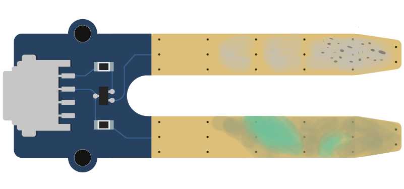
Figure 43: Corroded soil moisture sensor
We will go around the sensor corrosion by giving the sensor electricity only when it will actually need to measure the moisture. Sampling moisture is usually not done every second; once per minute or hour is perfectly fine. Let’s rewire the sensor so that it supports being on only when we make the measurement. Connect the VCC to the Arduino digital pin 8, the GND to Arduino GND, and the AO to Analog in 5 on the Arduino. Use the following code to turn on the sensor once per minute and then make a reading:
// we'll store reading from the input here int input; int vccPin = 8; // we'll map the input to the percentages here int val; void setup() { // initialize the serial communication Serial.begin(9600); // set up the pin mode pinMode(vccPin, OUTPUT); } void loop() { // turn on the sensor digitalWrite(vccPin, HIGH); // wait a little bit for the sensor to init delay(100); // read the value from the A5 input = analogRead(A5); // turn off the sensor digitalWrite(vccPin, LOW);
// map it to percentage val = map(input, 1023, 0, 0, 100);
// print and wait for a minute Serial.println(val);
delay(60000); } |
Using this code might save you a lot of probes because they go out fast if exposed to constant current. Many people that start to use Arduino in gardening are often surprised by this effect, but this is actually a known issue when using Arduino for gardening. Also, there are more expensive sensors available that can last significantly longer, but the solution where an inexpensive sensor is used with a little bit of smart code is what Arduino is all about.
Measuring Environment Conditions Conclusion
This is a very important chapter to many people. Measuring the environment conditions is one of the top reasons why they even start with the Arduino in the first place. People simply want to know what the temperature in the room is while they are away, or are simply interested what’s going on in environments when they are not around.
Most of those concerns are related to the energy costs, environmental concerns, and savings. The heating does not have to be on all of the time. By using Arduino in combination with some sensors, we can look at the historic data or chart them to a graph, and quickly determine where potential savings could be made.
There are also people with health issues and they want to specifically target an exact level of humidity in their environment; Arduino can be of great help there, too. One of the main advantages of Arduino as compared to ready-made solutions is that you can always tweak it to match only your needs—without having to acquire expensive devices when you only need just a part of their functionality.
Also, there are more and more people who want to eat healthier, and they are starting to grow their own food (well, perhaps not all of their food but at least some). There is a significant movement called Urban Gardening (UG) and Arduino is definitely a go-to technology in many UG-related applications. But the possibilities of Arduino do not end with just the environmental conditions. Actually, Arduino can be used to do a lot more. We will cover it in the next chapter.
- 1800+ high-performance UI components.
- Includes popular controls such as Grid, Chart, Scheduler, and more.
- 24x5 unlimited support by developers.