
Arduino Succinctly®

CHAPTER 6
Detecting Objects
By now, we learned how to monitor environment properties. But, often we will want to react to a physically changing environment or other objects moving or performing actions around us. That kind of sensing electronics is already used in everyday life.
For instance, if you ever drove a car backward and had parking sensors, you probably were already using object detection technology. Another popular technology for sensing is the intruder detection in various alarm systems. We will describe how those systems work, too.
Detecting objects is often not a binary business, and we will want a level of configuration. So, in this section, we will start with something simple that does not have a direct and obvious connection with the sensor for detecting objects. But it’s actually very important because we won’t always want the detecting components to react if the values pass or fall below a predefined value. But we will want to be able to define the sensitivity level, without having to reprogram the whole Arduino project. The component that enables us to make variable settings is called a potentiometer. Basically, what it does is change its electrical resistance when we turn a knob around. We will use a potentiometer to change sensitivity level in later examples. Let’s start with the potentiometer.
Using Potentiometers
Potentiometers usually come in the form of a turning knob. This knob provides more resistance the more it is turned. It is usually used to control the volume on radios, fan speeds on ventilation systems, or the desired temperature level in rooms. You probably have used it by now at least once in your life, but let’s look at how it works and how we can put it to use.
Parts list for this section:
- Arduino Uno
- USB cable
- 10K Ohm potentiometer
- Breadboard
- 3x Breadboard jumper wire
The wiring for the example is relatively simple. Keep in mind that it doesn’t really matter how you connect the positive and negative pins to the potentiometer. The only thing that will change if you make different wiring for the positive and the negative pins is that the resistance will change from a smaller to a larger value when you turn the knob, or the other way around. It all depends upon how you connected it. Let’s look at the wiring:
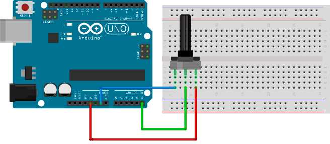
Figure 44: Potentiometer wiring
Use this programming example to see what’s going on:
// we'll store reading from the input here int input; // we'll map the input to the percentages here int val; // for keeping the previous reading int previous_val; void setup() { // initialize the serial communication Serial.begin(9600); } void loop() { // read the value from A5 input = analogRead(A5);
// map it to percentage val = map(input, 1023, 0, 0, 100);
// if percentage changed if (val != previous_val) { // print and store the value for comparison Serial.println(val); previous_val = val; } // delay to prevent output overcrowding delay(100); } |
If you turn the knob, you should see how the percentage changes from 0 to 100. If you don’t like the direction the value rises or falls, you have two options. One option is to exchange the rightmost and the leftmost connectors as previously mentioned. Try it out and see how the knob behaves, and then reconnect it so that we can see how to do it with the software:
val = map(input, 1023, 0, 100, 0); |
It is really up to you how you will adapt the reading values to the knob. The good thing about the analog components is that you instantly get the feedback no matter where and how you use them, so you can quickly compensate if you went in the wrong direction. Let’s start with another building block that is often used when detecting objects in the environment and especially for measuring the distance. Depending upon the Arduino build, it might disconnect or stop sending data in the minimum and maximum potentiometer rotation points. If that happens, disconnect the Arduino and reconnect it.
Using Ultrasonic Distance Sensor
Ultrasonic distance sensors are a very inexpensive and practical way to check how far something is. Sound travels through the atmosphere at a known speed. The speed can vary depending upon the weather conditions but, according to Wikipedia, sound passes a mile in 4.689 seconds or a kilometer in 2.914 seconds. The basic working principle behind the sensor is that we simply measure the time it takes between emitting an ultrasonic sound wave and then waiting for it to come back. Then, we divide the time by two because the wave traveled double the distance. Then we simply divide this duration by the speed of sound. The basic functioning principle is shown in the following figure:
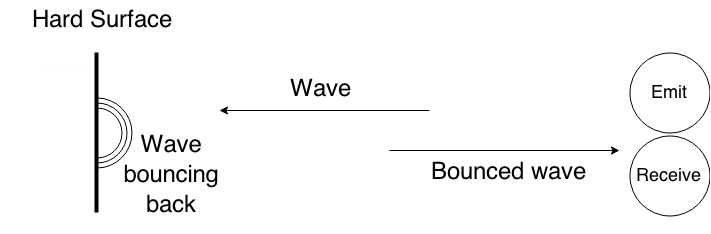
Figure 45: Ultrasonic distance sensor basic working principle
The previous figure shows two components. One is for emitting and the other is for receiving the sound wave. The ultrasonic distance sensor looks similar to the two circles displayed. It’s shown in the following figure:
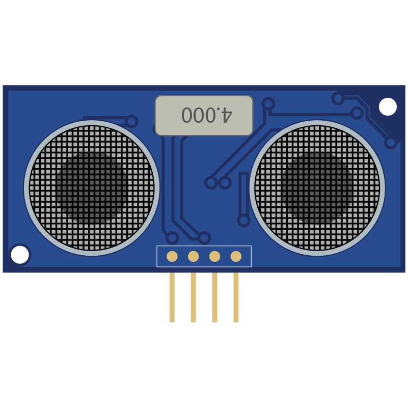
Figure 46: Ultrasonic distance sensor
The module used in our case is very accessible and inexpensive; its designation is HC-SR04 and it is in the parts list for this section.
Parts list for this section:
- Arduino Uno
- USB cable
- HC-SR04 Ultrasonic distance sensor
- Breadboard
- 4x Breadboard jumper wire
The basic overview of the wiring is show here:
Table 3: HC-SR04 Pins and Connections to Arduino
Pin | Connection |
|---|---|
Vcc | Pin for connecting 5V + |
Trig | Connect to pin 13 in our example |
Echo | Connect to pin 12 in our example |
Gnd | Pin for connecting to GND on Arduino |
The following figure shows the complete wiring:
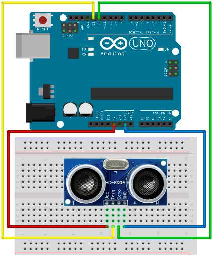
Figure 47: Ultrasonic distance sensor wiring
We will use the sensor to measure how far the nearest hard surface is and then display the distance to the serial port every second. In later examples, we will perform actions upon detecting objects at a certain distance but, for now, we will just look at what’s going on. Do note that the sound doesn’t bounce back very well from clothes, so the sensor might not read everything as you would expect. Here’s the code for the example:
// we'll use trigPin for emitting int trigPin = 13; // we'll listen for the pulse on the echoPin int echoPin = 12; // variables for calculations long duration, distance_inch, distance_cm; void setup() { // initialize serial communication Serial.begin (9600);
// initialize pins pinMode(trigPin, OUTPUT); pinMode(echoPin, INPUT); } void loop() { // emit a pulse digitalWrite(trigPin, HIGH); delayMicroseconds(10); digitalWrite(trigPin, LOW);
// get the time that it takes for the pulse to return // pulseIn waits for the pulse and returns number of microseconds // divided by two because sound travels there and back again duration = pulseIn(echoPin, HIGH) / 2;
// convert to inches and centimeters by using this formula distance_inch = duration / 74; distance_cm = duration / 29;
// print the results Serial.print(distance_inch); Serial.print(" inch; "); Serial.print(distance_cm); Serial.println(" cm"); Serial.println("");
delay(1000); } |
If you open up the Serial Monitor tool, you should see how the distance changes as you put something in front of the distance sensor. You can even take a ruler and check the precision of the sensor. Do note that there might be minor differences depending upon what altitude you live and the weather conditions during your experiments. Also, the sensor can’t detect when the objects are too close to it. It’s also not possible to measure distances that are below 2cm (0.8 inch) and beyond 400 cm (157.5 inch). In the next section, we will perform actions if the object comes too near to the sensor.
Reacting On Approaching Objects
Most of the time, the sensors are not used just to measure how far something is. Usually we want some kind of action performed, such as turning on a light, starting a beep, or turning on an alarm. In this section, we will work on the previous example and use LEDs to mimic a simple alarm.
If everything is fine, the green LED will be on. But if something approaches too near to the sensor, we will turn the red LED on. The parts list will be a little longer than in the previous section.
Parts list for this section:
- Arduino Uno
- USB cable
- HC-SR04 Ultrasonic distance sensor
- 2x 100 Ohms Resistor
- 1x Red LED
- 1x Green LED
- Breadboard
- 8x Breadboard jumper wire
The wiring for the example is shown here:
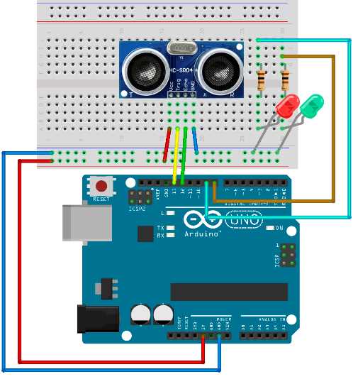
Figure 48: Distance alarm wiring
The code for the example:
// we'll use trigPin for emitting int trigPin = 13; // we'll listen for the pulse on the echoPin int echoPin = 12; int okPin = 8; int nOkPin = 9; // variables for calculations long duration, distance_inch, distance_cm; void setup() { // initialize pins pinMode(trigPin, OUTPUT); pinMode(echoPin, INPUT); pinMode(okPin, OUTPUT); pinMode(nOkPin, OUTPUT); } void loop() { // emit a pulse digitalWrite(trigPin, HIGH); delayMicroseconds(10); digitalWrite(trigPin, LOW);
// get the time that it takes for the pulse to return // pulseIn waits for the pulse and returns number of microseconds // divided by two because sound travels there and back again duration = pulseIn(echoPin, HIGH) / 2;
// convert to inches and centimeters by using this formula distance_inch = duration / 74; distance_cm = duration / 29;
// the distance is the same in both units // leave the one that suits you if (distance_cm < 28 || distance_inch < 11) { digitalWrite(nOkPin, HIGH); digitalWrite(okPin, LOW); } else { digitalWrite(okPin, HIGH); digitalWrite(nOkPin, LOW); }
delay(200); } |
Tuning the Distance Sensor on the Fly
The previous example is always fixed to turn the warning LED on if the object comes closer than a predefined value. In most real-life situations, having a fixed value is not enough. There are situations in which we will want to tune the distance that our sensor is detecting. To overcome this shortcoming of our current solution, we are going to add a potentiometer to the game. We had a section a little while ago about how it works, so feel free to look back on it to refresh yourself with it a bit. We’ll start with the parts list.
Parts list for this section:
- Arduino Uno
- USB cable
- HC-SR04 Ultrasonic distance sensor
- 2x 100 Ohms Resistor
- 1x Red LED
- 1x Green LED
- 10K Ohm potentiometer
- Breadboard
- 11x Breadboard jumper wire
We will regulate the alarm distance with the potentiometer. The minimum and the maximum values for the sensor are provided in the specification. We will use that in the example. We will also map the values that we read from the potentiometer to percentages. Then we will use the percentages to calculate the actual distance where the alarm is going to go off. We didn’t mention it earlier, but the sensor will not be correct in all of the readings. If the reading is smaller or greater than what the sensor is capable of detecting, then we will simply skip a cycle for reacting and continue with the new one. The wiring is a bit more complicated than with the previous example:
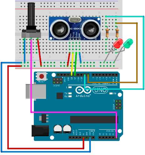
Figure 49: Distance alarm with regulating potentiometer
The code uses a bit more Arduino pins than in the previous sections. If you are using some other sensor for detecting the distance, please change the ranges in the code. This is the code listing for the example:
// we'll use trigPin for emitting int trigPin = 13; // we'll listen for the pulse on the echoPin int echoPin = 12; int okPin = 8; int nOkPin = 9; // sensor limits are defined in cm int sens_min = 2; int sens_max = 400; // variables long duration, distance, tune_in, alarm_distance; void setup() { // initialize pins pinMode(trigPin, OUTPUT); pinMode(echoPin, INPUT); pinMode(okPin, OUTPUT); pinMode(nOkPin, OUTPUT); } void loop() { // check the current tuned setting tune_in = map(analogRead(A5), 1023, 0, 0, 100);
alarm_distance = sens_min + ((sens_max - sens_min) * tune_in)/100;
// emit a pulse digitalWrite(trigPin, HIGH); delayMicroseconds(10); digitalWrite(trigPin, LOW);
// get the time that it takes for the pulse to return // pulseIn waits for the pulse and returns number of microseconds // divided by two because sound travels there and back again duration = pulseIn(echoPin, HIGH) / 2;
distance = duration / 29;
// sanity check on the values if (distance > sens_max || distance < sens_min) { return; }
// check if the alarm LED should light up if (distance <= alarm_distance) { digitalWrite(nOkPin, HIGH); digitalWrite(okPin, LOW); } else { digitalWrite(okPin, HIGH); digitalWrite(nOkPin, LOW); }
delay(200); } |
When you are done with the wiring, change the potentiometer and see how the alarm starts to react to proximity. With this example, we covered the basic usages of the distance sensor. We have covered a lot but the examples were more or less stationary. In the next section, we will take a small step towards dynamic sensing.
Parking Sensor
We mentioned a parking sensor as one of the possible ways to use an ultrasonic distance sensor. In this section, we will go a step further and go through the steps needed to make one.
The wiring is a bit easier than in the previous example but the programming will be slightly complicated. The hardest part in this section will be the calculation of the beep intervals and making the buzzer beep the closer the object comes. As in the previous sections, we will start with the parts list.
Parts list for this section:
- Arduino Uno
- USB cable
- HC-SR04 Ultrasonic distance sensor
- 1x 100 Ohms Resistor
- Arduino compatible passive buzzer
- Breadboard
- 8x Breadboard jumper wire
The wiring for the example:
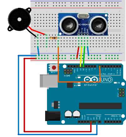
Figure 50: Park sensor wiring
The code is a bit more complicated than in the previous sections. The most complicated part is determining the interval between the beeps depending on the object distance:
// we'll use trigPin for emitting int trigPin = 13; // we'll listen for the pulse on the echoPin int echoPin = 12; // pin for the buzzer int buzzPin = 7; // sensor limitations defined in cm int sens_min = 2; int sens_max = 400; // buzzer limitations are defined in cm // it starts buzzing when something is closer than 100 cm long buz_min = 2; long buz_max = 100; // beeping intervals in seconds // this will be a long beep int beep_max = 700; // short beep int beep_min = 50; // variables for calculations long duration, distance, beepInterval; float pulsePercent; // we'll initialize the lastBuzzTime to 0 long lastBuzzTime = 0; void setup() { // initialize pins pinMode(trigPin, OUTPUT); pinMode(echoPin, INPUT); pinMode(buzzPin, OUTPUT); } void loop() { // emit a pulse digitalWrite(trigPin, HIGH); delayMicroseconds(10); digitalWrite(trigPin, LOW);
// get the time that it takes for the pulse to return // pulseIn waits for the pulse and returns number of microseconds // divided by two because sound travels there and back again duration = pulseIn(echoPin, HIGH) / 2;
distance = duration / 29;
// sanity check on the values if (distance > sens_max || sens_min < 2) { return; }
// if distance is smaller than the beeping trigger distance, start beeps if (distance < buz_max) { // the easiest is to calculate the percentages of min and max distance pulsePercent = (100 * (distance - buz_min) / (buz_max - buz_min));
// determine the beeping interval with the help of percentages beepInterval = beep_min + (pulsePercent * (beep_max - beep_min)) / 100;
// we will emit a tone without using the delay function // so we will check the Arduino internal clock to check when to beep if ((millis() - lastBuzzTime) >= beepInterval) { tone(buzzPin, 2200, 100); // we have to remember the last time we started a beep so that we don't // start to emit a continuous sound lastBuzzTime = millis(); } }
// minimum sensing time is the minimum beep interval delay(beep_min); } |
Now try it out with the palm of your hand. The closer you get to the sensor, the time between the beeps get shorter. Note that the ultrasonic distance sensor works best on hard surfaces and that the beep might be a bit irregular if you are far away from the sensor. In that case, take any kind of object with a hard surface and try to see how the sensor reacts to it.
With the hard surface object, you should get much better results than with the palm of your hand. Also, the distance sensor sometimes doesn’t detect surfaces that are parallel to it or at a greater angle because the sound beam bounces back in such a direction that it doesn’t come back to the sensor. Most of the cars have multiple sensors in the fender because of that.
Also, some of the older sensors didn’t detect small vertical obstacles such as poles and similar objects. But this sensor is a great fit for inexpensive projects and is often used in robotics. There are many Arduino robot designs out there that use this sensor to detect obstacles such as walls. The sensor is often mounted on turrets to give the robot more possibilities to detect obstacles. The sensor also has a very interesting shape because the emitter and the receiver look like eyes and the robot gets a very interesting form. In a way, the sensor represents its eyes.
Using Infrared Motion Sensor
Up until now, we have used an ultrasonic distance sensor in our examples. If you built the examples, you might have noticed that the ultrasonic distance sensor can’t always detect objects that don’t have a hard surface, or if the surface reflects the waves in such a way that they don’t return back to the sensor. It also has relatively moderate capabilities in the sense of distance and can’t detect something that’s beyond four meters or 157 inches.
Also, sometimes it’s not important how far something is, and we generally just want to detect whether or not somebody is in the room or if something is moving. An infrared sensor is a great fit for those situations, so we will use it in this section. We will build a movement detector with two LEDs. If nothing is moving, the green LED will be on. If something starts to move, we will turn the red LED on.
Parts list for this section:
- Arduino Uno
- USB cable
- Arduino-compatible infrared sensor
- 2x 100 Ohms Resistor
- 1x Green LED
- 1x Red LED
- Breadboard
- 7x Breadboard jumper wire
Wiring:
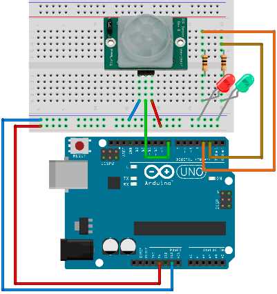
Figure 51: Motion sensor wiring
The sensor wiring may vary from producer to producer. Just to make sure, double check the wiring with the following table:
Table 4: Infrared Sensor Wiring for the Example
Pin | Connection |
VCC | Pin for connecting 5V + |
OUT | Connect to pin 8 in our example |
GND | Pin for connecting to GND on Arduino |
The code for the example is relatively simple. We will read the state from the input pin and then turn the LEDs on and off, depending upon what we read from the input:
// detection is going to be on pin 8 int detectPin = 8; // LED pins int greenPin = 2; int redPin = 3; int detectPinValue = LOW; void setup() { // initialize pins pinMode(detectPin, INPUT); pinMode(greenPin, OUTPUT); pinMode(redPin, OUTPUT); } void loop() { // check the value from the sensor detectPinValue = digitalRead(detectPin);
if (detectPinValue == HIGH) { // if sensor detected movement, turn the red LED on digitalWrite(greenPin, LOW); digitalWrite(redPin, HIGH);
// we'll leave the red LED on for a while delay(500); } else { // turn the green LED on digitalWrite(greenPin, HIGH); digitalWrite(redPin, LOW); }
// relatively short loop cycle delay(100); } |
This is a very interesting example. Move around the sensor to see how it reacts. Try not to move with your whole body but just move your hand to see what happens. This example is a nice basis for creating an alarm device. Another usage for this sensor is turning the light on so that we can see the path to the door without having to use a remote or something similar. In the next section, we will set up a motion sensor that turns an LED on when movement is detected, but only if the room is dark.
Turning the Light on Conditionally
One of the common usages of the motion sensor is to turn the light on and off when somebody approaches. The sensor works in the nighttime as well as in the daytime. But during the day, we would like to save electricity and not turn the light on because there is enough light. In this section, we will go through the wiring and the programming to do so. As with all of the examples, we will start with the parts list.
Parts list for this section:
- Arduino Uno
- USB cable
- Arduino-compatible infrared sensor
- 1x 10k Ohm resistor
- 1x GL5528 Photo Resistor or any 10K Ohm Photo Resistor
- 1x 100 Ohms Resistor
- 1x Yellow LED
- Breadboard
- 9x Breadboard jumper wire
The 10k Ohm resistor is paired with the photo resistor. The 100-Ohm resistor is paired with the LED as in the previous examples. We will use a yellow LED because it mimics the light bulb that’s supposed to be turned on. We mentioned earlier that we would not show you any circuits with the strong currents, so here we are just using the LED. But the LED could easily be replaced with the relay and you would have the real thing. But at this stage of development, it’s better not to play around with the dangerous currents. Let’s have a look at the wiring:
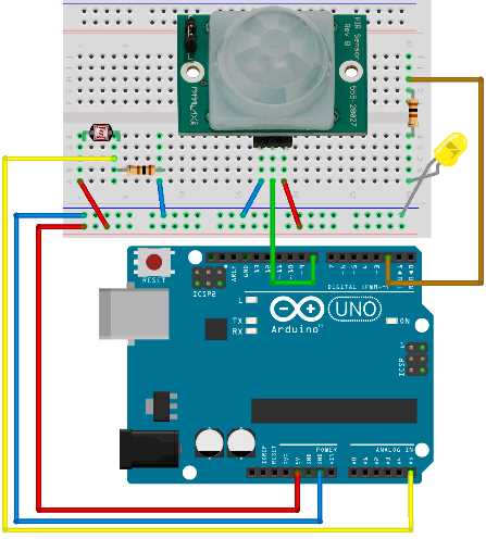
Figure 52: Conditional light on with motion sensor wiring
All that is missing is the code. We will make the timings a little bit shorter than in the real circuit. For instance, the light will remain on for around five seconds after the last registered movement. If you were building a real conditional light, we would leave the light on for couple of minutes after the last detected motion. Also, the software we are making here would definitely be in a higher price range because the sensor monitors for the last movement. Usually the lighting solutions just turn themselves on and wait no matter what, and after the time expires, they turn themselves off and wait for the new movement again. This example constantly monitors the space and continues to provide the light five seconds after the last movement is registered. If you are trying the example in a very light or dark room, tune the startTurningLightAt variable to your needs. It’s best that you experiment with the value and see what happens:
// movement detection is going to be on pin 8 int detectPin = 8; int detectPinValue = LOW; // light pin is going to be on pin2 int lightPin = 2; // we'll store reading value here int lightLevel, lightReading; // give this a bigger value in a light room int startTurningLightAt = 70; long lastMovementTime = 0; // continue with light 5 seconds after last movement int continueLightTime = 5000;
void setup() { pinMode(lightPin, OUTPUT); } void loop() { // read the light level from pin A5 lightReading = analogRead(A5);
// we'll measure the input values and map 0-1023 input // to 0 - 100 values lightLevel = map(lightReading, 0, 1023, 0, 100);
if (lightLevel < startTurningLightAt) { detectPinValue = digitalRead(detectPin);
if (detectPinValue == HIGH) { digitalWrite(lightPin, HIGH); lastMovementTime = millis(); } else if ((millis() - lastMovementTime) > continueLightTime) { digitalWrite(lightPin, LOW); } } else { digitalWrite(lightPin, LOW); }
delay(100); } |
This is the last example in the detecting objects section. For the better part of the chapter, we have been using two of the most popular sensors in the Arduino world: the ultrasonic distance sensor and the infrared movement sensor. We also showed the classical examples seen in everyday life involving those two. In the next chapter, we will give an overview of the most common Arduino networking solutions.
- 1800+ high-performance UI components.
- Includes popular controls such as Grid, Chart, Scheduler, and more.
- 24x5 unlimited support by developers.