
Arduino Succinctly®

CHAPTER 2
Building Circuits with LEDs
Building circuits with LEDs is a great way to learn about electronics and the Arduino. It’s relatively easy to debug everything because the LED is either on or it isn’t, so if something unexpected flashes, you probably have some kind of error. In the next step, we will use just one LED. Take any LED with two legs that you have available and it should look something like this:
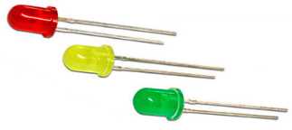
Figure 16: Various color LEDs
Now, most of you have heard about LEDs by now. What’s specific with LEDs here is that they let the current through in one direction only, so you have to be careful when making circuits with them because they won’t flash if you wire them the wrong way. Basically, you have to determine which leg is a plus and which leg is a minus. There are two ways to find this out:
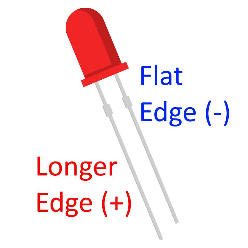
Figure 17: Determining the positive and negative lead on a LED
Most of the time, you’ll be looking for a longer leg, and you’ll connect it to a plus. If the legs have been cut off and you need to find out the polarity of the legs, you can find the negative leg by looking at a flat edge near the leg (on the outer casing of the LED). There is one important fact about LEDs that you have to remember. They have a bit of a self-destructive nature. They will draw as much current as possible until they burn out. To prevent this behavior, we must use an electronic element called a resistor. A resistor will limit the amount of current available to the LED and it will prevent the LED from self-destruction.
The amount of resistance a resistor is making is measured in Ohms. There is some calculation involved when determining the right resistor for the LED. You would have to look into the specifications of the LED and then fill out the sheet available here to find the right amount of resistance. With the Arduino, there are not that many voltages available. It’s always either 3.3 or 5 volts. I like to stay on the safe side with LEDs so I’ll be using a 100-Ohms resistor for 3.3-volt LEDs and a 220-Ohms resistor for 5-volt LEDs. You can fine-tune this to your own purposes, but generally, you’ll need only two types of resistors when working with Arduino and LEDs.
To start with an actual LED, you don’t need any kind of resistor at all. To begin, all you need is just an ordinary LED. If you followed along in the previous section, you’ve already uploaded a LED-blinking program. Now pin 13 already has a built-in resistor, so you don’t need an additional one for the next example. And right next to pin 13, there is a Ground pin. The makers of the Arduino did this intentionally so that we can try out our next example. Put the longer leg called the diode into pin 13 and the shorter pin into GND. If you are not sure about the location of the digital pin 13, flip the Arduino sideways and insert the legs into holes:
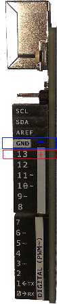
Figure 18: An Arduino Uno board viewed sideways
If you properly inserted the LED, you should see it blinking in the same rhythm as the onboard LED. Your Arduino is now controlling an electronic component. If it’s a bit dark in the room, turn the light off and enjoy the scene. But this is only the beginning. We’ll build on top of that in the next section.
Arduino Traffic Light
Parts list for this section:
- Arduino Uno
- USB Cable
- 3x 100-Ohms resistor
- Breadboard
- 1x 5mm Red LED
- 1x 5mm Yellow LED
- 1x 5mm Green LED
- 4x Breadboard jumper wire
The wiring for the example looks like this:
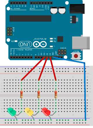
Figure 19: Arduino Uno traffic light wiring
We will connect the red LED to pin 13, the yellow LED to pin 12, and the green LED to pin 11. We will put around the same amount of time for the red and the green light. The transition from red to green will be a bit faster. The transition from green to red usually takes a bit longer. Let’s look at the code:
void setup() { // initialize red light pin pinMode(13, OUTPUT); // initialize yellow light pin pinMode(12, OUTPUT); // initialize green light pin pinMode(11, OUTPUT); } void loop() { // turn the red light on digitalWrite(13, HIGH); digitalWrite(12, LOW); digitalWrite(11, LOW); // wait delay(5000);
// turn the yellow light on together with red // at least that's the way they work in some parts of Europe digitalWrite(13, HIGH); digitalWrite(12, HIGH); digitalWrite(11, LOW); // wait delay(1000);
// turn the green light on digitalWrite(13, LOW); digitalWrite(12, LOW); digitalWrite(11, HIGH); // wait delay(5000);
// turn the yellow light on digitalWrite(13, LOW); digitalWrite(12, HIGH); digitalWrite(11, LOW); // wait delay(1000);
//start over } |
While you upload the code to the Arduino board, the red LED will be blinking. This is intentional so that you know that pin 13 goes randomly up and down while the program is uploading. This way, you don’t attach some moving or sensitive component to it in the future. For our traffic light, this simply brings more fun to the uploading. When the program starts to run, the first light will be red. Then the yellow light will be shown. In Europe, the red light goes on together with the yellow one before the traffic light shows the green light. We will emulate this behavior just so that you can see that two LEDs can be on at the same time. Arduino will continue to switch from red to green light and back again, for as long as it has power.
There is one very important component that’s new in this example, and that’s the breadboard. The breadboard is a useful component because a person does not have to know much about soldering to get started with the electronics. It certainly helped me a lot when I was starting out. One other advantage of using a prototyping board is that it doesn’t take long to build basic circuits, and you can rearrange components quickly if something is wrong. Under the holes of a prototyping board are wires, such as this:
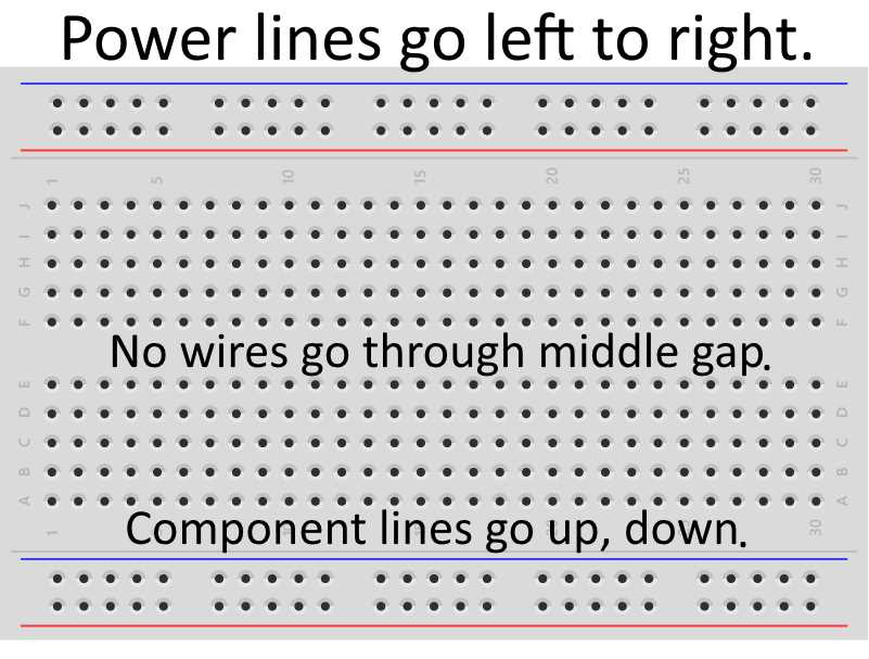
Figure 20: Prototyping board wiring
The downside of a prototyping board is that it can’t accommodate a lot of components and that, with soldering, our circuits will be a lot smaller. But, for someone just going into building electronic circuits, it’s a perfect starting point. It’s hard to summarize the do’s and don’ts of using a prototyping breadboard. You will get a feel for how to use the prototyping board as you progress, by looking at the examples in future sections.
The assumption is that most people reading this book will come from a software development background. There is one important thing we need to point out when it comes to the breadboard (and to electronic circuits in general). Some bugs are harder to find because, aside from the software component, there is a possibility of wrong wiring. Some of the wrong wiring might come from misunderstanding how the lead wires are connected in the prototyping board.
One of my biggest misunderstandings was when I bought a breadboard with multiple power lines but they didn’t go all the way from the left to the right of the board. They have a break in the middle of the power lines, and that is how the longer breadboards work. If you are unaware of this fact, you might expect that the components will be under power. But they wouldn’t work because power rails stop in the middle and you have to connect them with additional wires to ensure that they get the current. You can, potentially, lose a lot of time until you find what’s actually going on. There are versions of a breadboard where there is no break in the middle but, just so that you are aware of the gap between the power lines on bigger breadboards. I’ll depict the gap with a red line on the following figure:
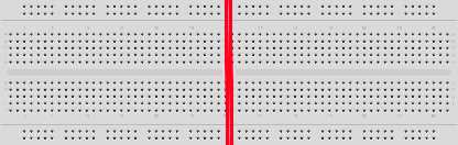
Figure 21: Un-bridged gap between the power lines in the middle of a bigger breadboard
Arduino Cylon Eye
Parts list for this section:
- Arduino Uno
- USB cable
- 10x 100-Ohms resistor
- Breadboard
- 10x 5mm red LED
- 1x Breadboard jumper wire; up to 11 wires if your resistors have short leads
I won’t talk much about the Cylon Eye effect; look it up if you are not familiar with it. From an electronics angle, it’s a red light going constantly from left to right. I will try to save some wires with this example, so I’ll show you how to make a version with just one wire for the whole wiring. But you can also use one wire per LED as in the previous example; it’s completely up to you. Here’s an example with just one wire:
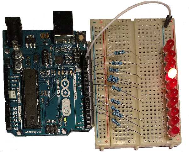
Figure 22: Cylon Eye version with a single jumper wire
The first LED is plugged into an Arduino digital pin 4. The last one is digital pin 13. Do not forget to connect every pin to a resistor before you hook it up to the LED. Also, don’t forget to double-check the polarity of the LEDs because the example will not work at all if you connect the negative LED leg to the pin output. You might be wondering what’s wrong when, in fact, all you did was turn the LED the wrong way. This happens a lot, especially if somebody is just starting out. Because of the viewing angle, it might be a bit hard for you to read the pin connections from the previous figure, and to know where you have to insert the leads from the components. So here’s a complete schematic to help you. Just as a precaution, remember, there are 10 LEDs in a row altogether:
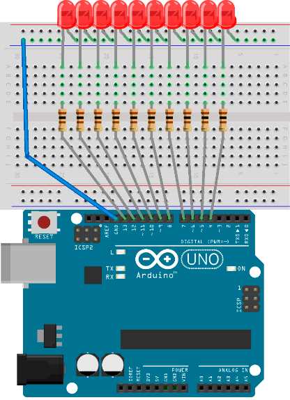
Figure 23: Cylon Eye wiring schematics
The number of LEDs that we control in this example is significantly larger than in the previous section. We’ll have to use looping construct when controlling all of the LEDs. Here is the code:
// define the starting pin as a constant const int startPin = 4; // total number of LEDs const int numLEDs = 10; // current LED will go from 0-9 int currentLed = 0; // direction will be 1 and -1 int direction = 1; void setup() { // initialize the pins with a for loop for (int i = startPin; i < startPin + numLEDs; i++) { // set pin mode to output pinMode(i, OUTPUT); } } void loop() { // turn the led on digitalWrite(startPin + currentLed, HIGH); // wait for 100 ms delay(100); // turn the led off digitalWrite(startPin + currentLed, LOW);
// move to the next LED currentLed += direction;
// go back up if we've reached the bottom if (currentLed < 1) { direction = 1; } // go back down if we've reached the top if (currentLed >= numLEDs - 1) { direction = -1; } } |
I think this example looks best if viewed in the dark. So take some time to enjoy it. This example can serve as a good starting point for a great range of special LED light effects. Imagine you could change the color of the LEDs and put them in some random order when turning on and off. During the holiday season, you could give this as a gift. I don’t know why, but the light effects somehow always make people smile. If you built this example, try to play a bit with it and make various effects. In the next section, I will take it a step further.
Countdown
This example will be pretty much as complex as it gets on a small solder-less breadboard. We will use significantly more wires than in the previous sections. The number of LEDs is going to increase as well.
Parts list for this section:
- Arduino Uno
- USB cable
- 13x 100-Ohms resistor
- Breadboard
- 13x 5mm LED
- 18x Breadboard jumper wire
In this section, we are going to build a digit display out of 13 LEDs. Here’s the initial idea:
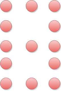
Figure 24: 13 LEDs in a single-digit display
And here it is in action where all of the 10 digits are displayed in a countdown:
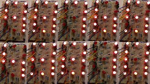
Figure 25: 13 LEDs countdown in action
The wiring of this example is a bit complex, especially if you are just beginning with the breadboard. Try to remain focused while building the example. You can rewire the example however you see best. Here is my complete wiring schema:
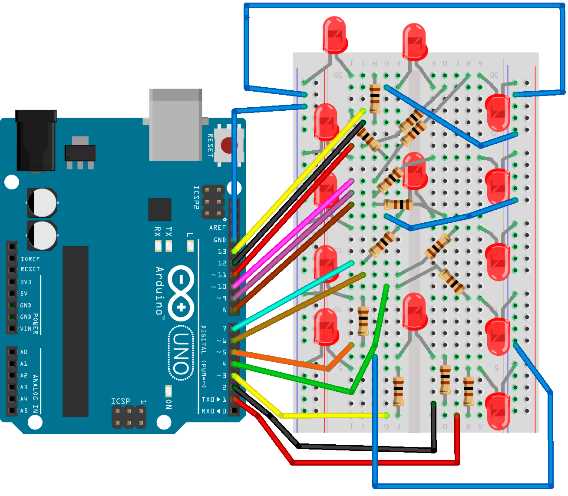
Figure 25: Countdown example wiring schema
This example is more for practicing. In practice, you would use a seven-segment display. But this is a section in which we are studying LED behavior, so we’ve built this example with LEDs and not seven segment displays. However, there is one more thing that you need in order to complete this example, namely, the code:
// define the starting pin as a constant const int startPin = 1; // total number of LEDs const int numLEDs = 13; // we'll start the countdown at 9 int count = 9; // here is each digit mapped to the state of the pins int numberMatrix[][13] = { {1, 1, 1, 1, 1, 1, 1, 0, 1, 1, 1, 1, 1}, // 0 {1, 0, 0, 1, 0, 1, 0, 0, 1, 1, 0, 0, 0}, // 1 {1, 1, 1, 0, 1, 1, 1, 1, 1, 1, 1, 1, 0}, // 2 {1, 1, 1, 1, 0, 1, 1, 1, 1, 1, 1, 1, 0}, // 3 {1, 0, 0, 1, 0, 1, 1, 1, 0, 0, 0, 1, 1}, // 4 {1, 1, 1, 1, 0, 1, 1, 1, 0, 1, 1, 1, 1}, // 5 {1, 1, 1, 1, 1, 1, 1, 1, 0, 0, 0, 1, 1}, // 6 {1, 0, 0, 1, 0, 1, 0, 0, 1, 1, 1, 1, 0}, // 7 {1, 1, 1, 1, 1, 1, 1, 1, 1, 1, 1, 1, 1}, // 8 {1, 0, 0, 1, 0, 1, 1, 1, 1, 1, 1, 1, 1}, // 9 }; void setup() { // initialize the pins with a for loop for (int i = startPin; i < startPin + numLEDs; i++) { // set pin mode to output pinMode(i, OUTPUT); } } void loop() {
// go through the pins for the current count, turn them on an off for (int i = 0; i < numLEDs; i++) { digitalWrite(startPin + i, numberMatrix[count][i]); }
// wait for a second delay(1000);
// count down count--;
if (count < 0) { // start over count = 9; // turn all the LEDs off for (int i = startPin; i < startPin + numLEDs; i++) { digitalWrite(i, LOW); } // wait for a second and start over delay(1000); } } |
- 1800+ high-performance UI components.
- Includes popular controls such as Grid, Chart, Scheduler, and more.
- 24x5 unlimited support by developers.